


3 -
C H A P T E R 3 : P R O C E D U R E S
3 - 1 0
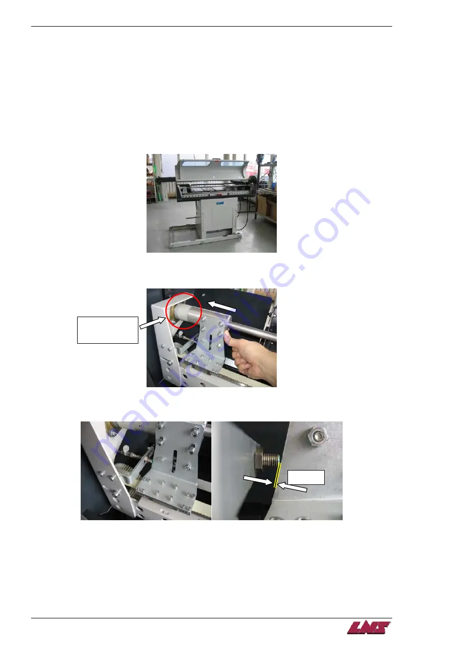
Home Position Proximity Switch SQ5 Adjustment
Conditions:
-
Bar feed power on.
-
Bar feed in
STOP
mode.
-
Pusher at the mechanical home position.
Procedure:
Step 1:
Open the main access cover.
Step 2:
Make sure the carrier is in home position.
Nylon bushing is
the mechanical
home position.
Step 3:
Adjust the SQ5 proximity switch position just far enough to get a strong signal from the switch (approx. 0,5
mm) and tighten down. Any slight movement forward of the carrier should deactivate the proximity sensor.
~0,5 mm
Step 4:
Close the main access cover.
Step 5:
Press the
[STOP]
key on the remote control to clear any alarm. Reference the bar feed (see "Reference
procedure").
Procedure complete.
QUICK LOAD SERVO 65/80
Summary of Contents for Quick Load Servo 65
Page 1: ...Troubleshooting manual ENG 9 020 01 ANG ...
Page 43: ......
Page 61: ......
Page 67: ......
Page 96: ...CHAPTER 6 SPARE PARTS QUICK LOAD SERVO 65 80 6 27 020 005 413 QLS 65 80 Locking block ...
Page 99: ...CHAPTER 6 SPARE PARTS 6 30 020 005 703 QLS 65 80 Sub assembly drive QUICK LOAD SERVO 65 80 ...
Page 101: ...CHAPTER 6 SPARE PARTS 6 32 020 005 723 QLS 65 80 Sub assembly cogwheel QUICK LOAD SERVO 65 80 ...
Page 115: ...CHAPTER 6 SPARE PARTS 6 46 020 011 013 12 QLS 65 Assembly pusher ø12 QUICK LOAD SERVO 65 80 ...
Page 116: ...CHAPTER 6 SPARE PARTS QUICK LOAD SERVO 65 80 6 47 020 011 013 20 QLS 65 Assembly pusher ø20 ...
Page 117: ...CHAPTER 6 SPARE PARTS 6 48 020 011 023 6 QLS 80 Assembly pusher ø1 4 QUICK LOAD SERVO 65 80 ...
Page 118: ...CHAPTER 6 SPARE PARTS QUICK LOAD SERVO 65 80 6 49 020 011 023 12 QLS 80 Assembly pusher ø12 ...
Page 119: ...CHAPTER 6 SPARE PARTS 6 50 020 011 023 20 QLS 80 Assembly pusher ø20 QUICK LOAD SERVO 65 80 ...


