C H A P T E R 3 : P R O C E D U R E S
QUICK LOAD SERVO 65/80
3 - 1 5
Reference Procedure
Conditions:
-
Bar feed on.
-
Bar feed in
STOP
mode.
Procedure:
Step 1:
Press on the key corresponding to
[
]
on the remote control. Select menu
[4]
using the up/down arrow
keys. Press on the key corresponding to
[ENTER]
.
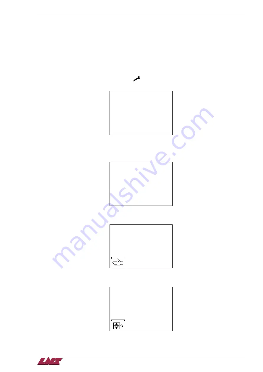
MAIN MENU
[1]
1:PART SETUP
2:APPLICATION SETUP
3:POSITION/TORQUE
4:MISC. FUNCTIONS
5:SERVICE
Step 2:
Press on the key corresponding to
[PAGE DOWN]
as many times as necessary until this text appears.
Select option
[2]
using the up arrow key. Once
[2]
is selected, press and hold
[ENTER]
for 2-3 seconds.
The screen will then return to the home page.
REQUEST FOR
REFERENCE POINT
[@]
1:NO
2:YES
ESC ENTER
Step 3:
Press on the key corresponding to
[MANUAL MODE]
.
LOADING CHANNEL IN
AN
INTERMEDIATE POSITION
- F1 MANUAL MODE
Step 4:
Press on the key corresponding to
[REFERENCE]
.
POSITIONING ERROR!
ENCODER LOST ITS
REFERENCE POINT...
RESET REFERENCE
POINT (ZERO POINT)
-F1 START
Summary of Contents for Quick Load Servo 65
Page 1: ...Troubleshooting manual ENG 9 020 01 ANG ...
Page 43: ......
Page 61: ......
Page 67: ......
Page 96: ...CHAPTER 6 SPARE PARTS QUICK LOAD SERVO 65 80 6 27 020 005 413 QLS 65 80 Locking block ...
Page 99: ...CHAPTER 6 SPARE PARTS 6 30 020 005 703 QLS 65 80 Sub assembly drive QUICK LOAD SERVO 65 80 ...
Page 101: ...CHAPTER 6 SPARE PARTS 6 32 020 005 723 QLS 65 80 Sub assembly cogwheel QUICK LOAD SERVO 65 80 ...
Page 115: ...CHAPTER 6 SPARE PARTS 6 46 020 011 013 12 QLS 65 Assembly pusher ø12 QUICK LOAD SERVO 65 80 ...
Page 116: ...CHAPTER 6 SPARE PARTS QUICK LOAD SERVO 65 80 6 47 020 011 013 20 QLS 65 Assembly pusher ø20 ...
Page 117: ...CHAPTER 6 SPARE PARTS 6 48 020 011 023 6 QLS 80 Assembly pusher ø1 4 QUICK LOAD SERVO 65 80 ...
Page 118: ...CHAPTER 6 SPARE PARTS QUICK LOAD SERVO 65 80 6 49 020 011 023 12 QLS 80 Assembly pusher ø12 ...
Page 119: ...CHAPTER 6 SPARE PARTS 6 50 020 011 023 20 QLS 80 Assembly pusher ø20 QUICK LOAD SERVO 65 80 ...


