background image

12

START UP MANUAL

QUICK LOAD SERVO S2

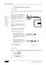
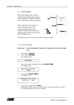
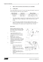
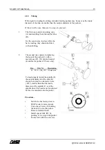
4.1.1 Mechanical stop

The feeding pusher of the Quick Load Servo bar feed system has a set length, which was
determined so that it can function with all types of lathes.

To make sure that they never collide with the clamping device (end of bar improperly
adjusted, or in manual mode, for example), the feeding pusher of the Quick Load Servo
comes with a mechanical safety stop.

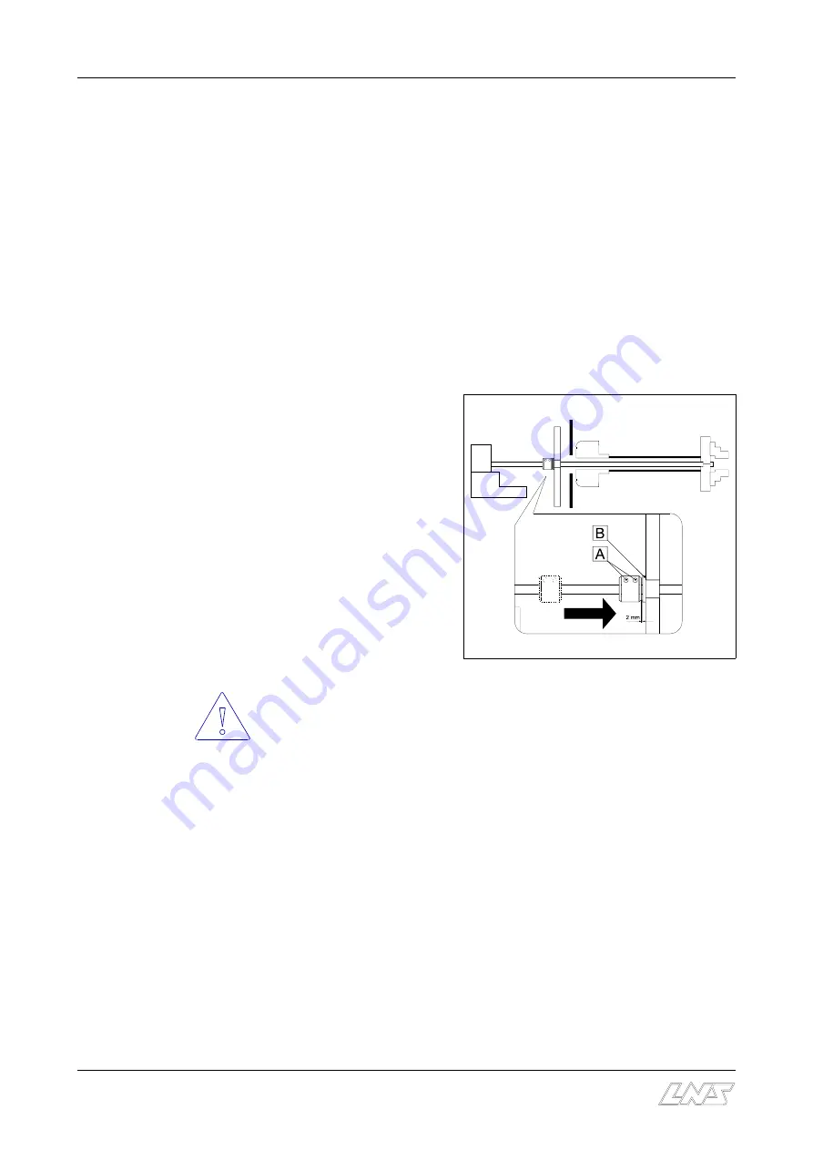
When the mechanical stop (stop sleeve) comes into contact with the guide bushing, the
feeding pusher is immediately stopped.
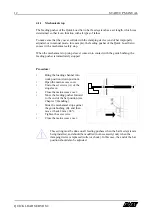
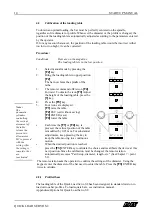
Procedure :

Bring the loading channel into
work position (down position).

• 

Open the main access cover.

Undo the set screws (A) of the
stop sleeve.

Close the main access cover.

Move the feeding pusher forward
to the end of the bar position (see
Chapter 7, Handling).

Slide the mechanical stop against
the guide bushing (B), and then
move it back 2 mm (.08"). 

Tighten the set screws.

Close the main access cover.

This setting must be done on all feeding pushers when the bar feed system is
being installed, and should be modified (not necessarily) only when the
clamping device is replaced (collet or chuck). In this case, the end of the bar
position should also be adjusted.

Summary of Contents for QUICK LOAD SERVO S2

Page 1: ...ENG MADE IN USA ...

Page 2: ...1 Example 1 Set up for round bars 7 8 3 2 Example 2 Set up for hexagonal bars 8 3 3 Example 3 Set up for square bars 9 3 4 Example 4 Set up for other bars 10 4 MECHANICAL SETTINGS AND OPTIONAL ACCESSORIES 11 4 1 Replacement of the feeding pusher 11 13 4 2 Calibration of the loading table 14 4 3 Slope of the magazine table 15 4 4 Loading fingers up 15 16 5 PUTTING THE LATHE INTO OPERATION 17 5 1 Sp...

Page 3: ...n divided into 4 categories Settings related to installation C End of bar position C Top cut position Settings related to bar stock and machined parts C Example 1 Set up for round bars C Example 2 Set up for hexagonal bars C Example 3 Set up for square bars C Example 4 Set up for other bars Mechanical settings and optional accessories C Replacement of the feeding pusher C Slope of the magazine tab...

Page 4: ...ck remnant Regardless of the length of the bars or parts the end of bar position is always the same In very special cases a different end of bar setting needs to be selected The length of the remnant may vary C The minimum remnant length Min is obtained when the feeding pusher is just behind the clamping device while the last part is being machined C The maximum remnant length Max is obtained when...

Page 5: ... press the key attributed to the icon to add the value or the key to substract it The display reads the new end of bar position C To exit the end of bar set mode press the key attributed to the icon ESC TEACH IN By teaching C Press the key attributed to the icon TEACH IN The display reads the current end of bar position C Press the key FWD and advance the pusher to the desired position see previou...

Page 6: ...amping device With this system the setting is the same for any bar length Top cut position setting Important Before handling the barfeeder stop the lathe at the end of part cycle 1 Press the key STOP 2 Press the key MENU The display reads MAIN MENU 3 Press twice the key attributed to the icon PAGE DOWN The display reads END OF BAR POSITION MM 4 Press the key PAGE DOWN The display reads POSITION OF...

Page 7: ...d to the icon TEACH IN C Press the key attributed to the icon START The loading channel raises and loads a bar as it passes by The feeding pusher inserts the bar into the lathe spindle The feeding pusher returns to its reference position The loading channel goes down The feeding pusher is now facing the spindle C Press the key FWD and advance the bar stock to the desired position see previous page...

Page 8: ...ENU Press the numeric key 1 Part Setup the displays reads LOADING OF 1 ROUND MATERIAL 2 HEXAGONAL 3 SQUARE 4 OTHERS On the keypad select 1 Round Press the ENTER key twice the remote station displays the following text NEW BAR STOCK DIAMETER On the keypad enter 200 Press the ENTER key twice the motor M2 engages and sets the loading table and the loading fingers of the bar magazine The remote comman...

Page 9: ...y reads LOADING OF 1 ROUND MATERIAL 2 HEXAGONAL 3 SQUARE 4 OTHERS On the keypad select 2 Hexagonal Press the ENTER key twice the remote station displays the following text NEW BAR STOCK DIAMETER On the keypad enter 650 Press the ENTER key twice the motor M2 engages and sets the loading table and the loading fingers of the bar magazine The remote command displays the following text INPUT OVERALL PA...

Page 10: ... HEXAGONAL 3 SQUARE 4 OTHERS On the keypad select 3 Square Press the ENTER key twice the remote station displays the following text NEW BAR STOCK DIAMETER On the keypad enter 400 Press the ENTER key twice the motor M2 engages and sets the loading table and the loading fingers of the bar magazine The remote command displays the following text INPUT OVERALL PART LENGTH On the keypad enter 600 which ...

Page 11: ...he keypad select 4 Other Press the ENTER key twice Unlike other profiles when Others is entered no diameter needs to be entered The remote station displays the following text INPUT OVERALL PART LENGTH On the keypad enter 25 which represents the sum of the bar length and the thickness of the cut off tool Press the ENTER key twice to store the data Press the ESC key to exit the set up functions A te...

Page 12: ...ameter pushers Their placement on the loading table will be determined by the length of the bars to be loaded Replacement Bring the loading channel into working mode position down position then place the bar feed system into the STOP mode remote station 1 Loosen the fastening screws A sufficiently to free the groove C that holds the pusher B in the connecting piece D 2 Slide the pusher forward by ...

Page 13: ...ing the feeding pusher is immediately stopped Procedure Bring the loading channel into work position down position Open the main access cover Undo the set screws A of the stop sleeve Close the main access cover Move the feeding pusher forward to the end of the bar position see Chapter 7 Handling Slide the mechanical stop against the guide bushing B and then move it back 2 mm 08 Tighten the set scr...

Page 14: ...sists in replacing the head of the pusher C with a special nose D 130 mm in diameter available for pusher Ø 25 mm only Des Ord Nr Description D 021 11 104_130 130mm disk To feed properly inside the spindle F the outside diameter of the disk D should be turned to a diameter 4 mm 015 smaller than that the inside diameter of the spindle F or of the spindle liner The head must be adjusted before it is...

Page 15: ...ote command offers icon F4 Forward To obtain the icon F3 Adjust the height of the loading table press the 1 key 4 Press the F3 key 5 Four icons are displayed F1 raise the table F2 ESC exit without saving F3 ENTER save F4 lower the table C Each time the F1 or F4 key is pressed the vertical position of the table is modified by 0 25 mm For substantial adjustments keep pressing the key to keep the tab...

Page 16: ...slope of the table varies If the range of adjustment is not enough remove the pin B lift and place the table on the next hole and replace the pin 4 4 Loading fingers set up The slope of the table barely affects the loading of bars of greater diameter However it is possible that the bars of small diameter may not load correctly For this reason the fingers must be adjusted whenever the slope of the ...

Page 17: ...lace two bars D on the table against the loading fingers E C Load manually to check the adjustment Fingers set up for loading round bars C Adjust the slope of the loading table to the round bar loading position C Adjust the stops by unscrewing the knurled handle B until the top nuts F rest against the block G in position 1 If the slope of the table must be adjusted between the two indicated positi...

Page 18: ... in terms of the diameter of the bar diameter of the bar 1 mm but should always be larger than that of the diameter of the feeding pusher To guarantee that the small feeding pushers dia 6 35 and dia 12 mm do not come into contact at any time with the walls of the reduction tube it is recommended to retract them from the spindle before the bar begins to rotate see Chapter 7 section 5 There are two ...

Page 19: ...e orientation When the material is located in the loading channel it is oriented so to speak in position The profile of the clamping device should be positioned with regard to the profile of the bar If the bar is of the same length as the spindle at the time it leaves the loading channel it should already be inserted into the clamping device If the distance between the front of the bar feed system...

Reviews: