
8
START UP MANUAL
QUICK LOAD SERVO S2
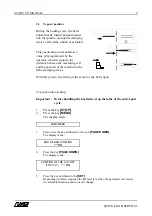
Note :
For more
information
concerning
the
parameters,
see Chapter 7,
point 5.
Note :
If the previous
profile was
"Other", a text
indicating that
the loading
table needs to
be adjusted
manually will
be displayed.
See point 4.2.
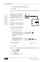
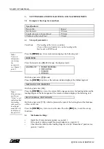
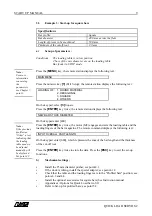
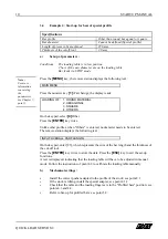
3.2
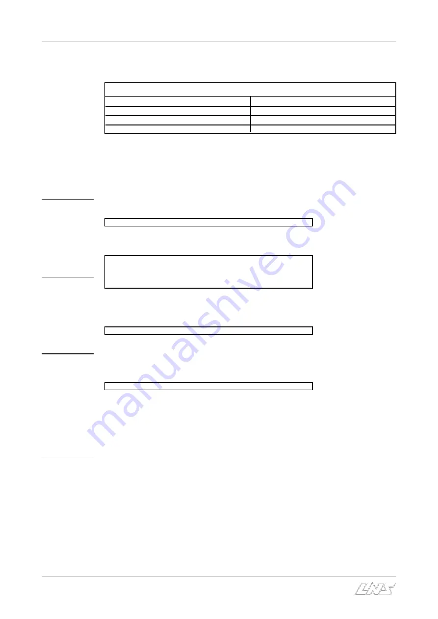
Example 2: Start-up for hexagonal bars
Specifications
Bar profile
Hexagonal
Bar diameter
65.0 mm
Length of pieces to be machined
37.0 mm
Thickness of the cutoff tool
2.0 mm
a)
Set-up of parameters :
Conditions:
The loading table is in low position
2 bars of the new diameter are on the loading table
Bar feeder in STOP mode
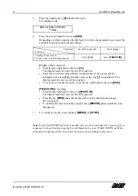
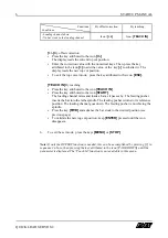
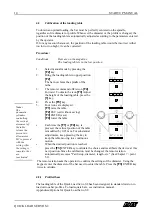
Press the
[MENU]
key; the remote station displays the following text :
MAIN MENU
Press the numeric key
[1]
(Part Setup); the display reads:
LOADING OF : 1. ROUND MATERIAL
2. HEXAGONAL
3. SQUARE
4. OTHERS
On the keypad, select
[2]
Hexagonal
Press the
[ENTER]
key twice; the remote station displays the following text:
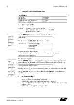
NEW BAR STOCK DIAMETER
On the keypad enter [650]
Press the
[ENTER]
key twice; the motor (M2) engages and sets the loading table and the
loading fingers of the bar magazine. The remote command displays the following text :
INPUT OVERALL PART LENGTH
On the keypad, enter [390], which represents the sum of the bar length and the thickness
of the cut-off tool.
Press the
[ENTER]
key twice to store the data. Press the
[ESC]
key to exit the set-up
functions.
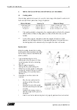
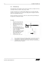
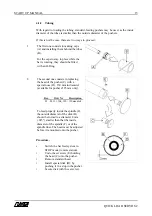
b)
Mechanical settings :
C
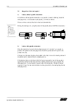
Install the 25 mm diameter pusher; see point 4.1
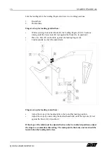
C
If the stock is tubing, install the special adapter; see point 4.1.2
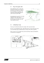
C
Check that the table and the loading fingers are in the "Profiled bars" position; see
points 4.3 and 4.4
C
Refer to Set-up for profiled bars; see point 5.2.
Summary of Contents for QUICK LOAD SERVO S2
Page 1: ...ENG MADE IN USA ...


