background image

S4 SERIES PHOTOELECTRIC PROTECTOR

INSTALLATION AND USAGE MANUAL

SHANDONG LAIEN OPTIC-ELECTRONIC TECHNOLOGY CO. ,LTD.

Please  read  this  document  carefully  and  thoroughly  before  installation  and  operation, 
because the correct and optimum use of this product is important for the personal safety.
Please give the user this document with the photoelectric protector if you are an agent, a 
dealer or a machine manufacturer which forms a complete set, because this document is 
important to guide the user correctly to install and operate.

Summary of Contents for S4 SERIES

Page 1: ...ly before installation and operation because the correct and optimum use of this product is important for the personal safety Please give the user this document with the photoelectric protector if you...

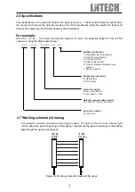
Page 2: ...ous points of operation and danger areas require safeguarding The protector only protects the rectangular region of the light curtain If it is installed not to be correct either operation is not accor...

Page 3: ...duction 8 3 2 The function and operation of the handheld device 9 3 3The function and operation of the self service software 10 4 Installation 4 1 To Determine a Safety Distance 12 4 2 To Determine Pl...

Page 4: ...sensors 7 1 Debugging of emitter and receiver 25 7 2 Operation Test of Entire System 25 8 Operation Check and Maintenance 8 1 Attention 26 8 2 Check and Maintenance 27 9 Simple Examination and Repair...

Page 5: ...ance determination of placement position and attentions for neighboring placement The function of S4 series parts and shell size Wiring contains wiring instruction for controller terminals wiring for...

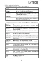
Page 6: ...1 IEC 62061 Safety of machinery Functional safety of electrical electronic and programmable control systems EN 292 Safety of machinery basic concepts general principles for design EN 999 Safety of mac...

Page 7: ...opto electronic protective devices GB 4584 2007 Specification of active opto electronic protective devices for presses GB T 15706 1 Safety of machinery Basic concepts general principles for design Pa...

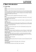
Page 8: ...lector the emitter and the receiver of the multi sides protection type produce the light curtain Light beam The emitter unit sends out the infrared light forms a bunch of parallel light after passing...

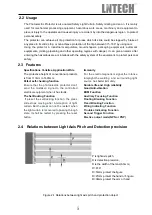
Page 9: ...pitch and protection object Specifications Varieties Application Wide The protective height of conventional products is from 113mm to 1493mm Pefect self checking function Ensure that the photoelectric...

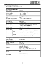
Page 10: ...ltage below 1 4V Response time 5 35ms Status indicator Emitter light passing green light intercepting red LED indicator light state fault indicator LED display Receiver light passing green light inter...

Page 11: ...bracket Additive information Y Integrated steel pipe bracket F Split steel pipe bracket Z Combine bracket W Right angle bracket S Double rotatable arms steel pipe bracket T Special request Output way...

Page 12: ...anking function set 2 blank two or less than two light beams protector is in the condition of light passing Blank more than two light beams protector is in the condition of light intercepting Set 5 bl...

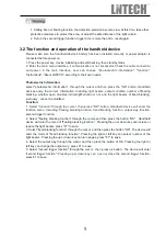
Page 13: ...lanking function output way function second trigger function 2 Select floating blanking function through the cursor and then press the button OK Handheld device will enter the menu of floating blankin...

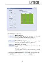
Page 14: ...cable to recever and USB control box 2 Open the S4 special self help software then enter user name and password default user name laienkeji password 00000000 Click the login button enter the followin...

Page 15: ...input the light beams as required and then click the floating blanking finally click save Setting second trigger function The mouse clicks the second trigger function button to open or close the func...

Page 16: ...llimeter mm 2 K Value Determination When the light curtain is installed in a horizontal position taken as 1600mm s for calculation When the light curtain is installed in a vertical position and the sa...

Page 17: ...l conditions that the photoelectric protector ensures to realize protection function must calculate the safety distance correctly B Installation must guarantee that minimum distance between light curt...

Page 18: ...opening the position of the highest light beam of the protector could not be lower than the up margin of mould opening The protection height of light curtain used on press must be insured Figure 4 2...

Page 19: ...iver it should be placement to reference the figure following Figure 4 3 Placement schematic drawing for prevented the neighboring light curtain disturbs mutually A The mutual disturbance between the...

Page 20: ...A The smooth reflecting surface around the light curtain can cause the protector to lose the normal function so as to lose the protective function B The placement position of the protector must be as...

Page 21: ...combination angle can be changed by changing the installation position The right angle bracket is simple and practical for fixing it is fixed through two right angle brackets with the sensor on mechan...

Page 22: ...18 Figure 4 7 Installation of combined brackets Figure 4 8 Right angle brackets...

Page 23: ...digital display Light passing indicator Light intercepting indicator Failure indication failure state 4 The top cover 5 Parts that connects the sensor and the signal cable 4 6 Installation tools Elect...

Page 24: ...4 773 S4 21 765 52 765 S4 36 750 26 750 S4 14 833 112 833 S4 21 825 56 825 S4 36 810 28 810 S4 14 893 120 893 S4 21 885 60 885 S4 36 870 30 870 S4 14 953 128 953 S4 21 945 64 945 S4 36 930 32 930 S4 1...

Page 25: ...guide safety relay or magnetic contact The figure below is the manual reset mode please connect the light red line red T to 24VDC if need automatic reset 6 1 Wiring of NPN Output Type Protector Figure...

Page 26: ...C Power Supply EDM Red T EDM Red T Shield Shield 0V Blue GND 0V Blue GND synchronizing signal line White CP synchronizing signal line White CP 24V Brown VDD 24V Brown VDD auxiliary output Black S2 Man...

Page 27: ...ue 0V GND 2 Brown DC12V or DC24V VCC 3 Green OSSD3 Aux output 4 White CP Link line between emitter and receive 5 Yellow EDM1 Relay detection 6 Red EDM2 Relay detection 7 Shield SHIELD Shield Receiver...

Page 28: ...5 Warning of wiring OSSD1 OSSD2 OSSD1 OSSD2 OSSD1 OSSD2 Separate OSSD1 and OSSD2 Don t connect OSSD1 and OSSD2 not sure the security of the signal Make sure the signal processing is separate from ano...

Page 29: ...eiver and emitter are bright D Check Check the protector is OK with intercepting every beam Intercepting the light intercepting indicator red is bright the light passing indicator green is dark Passin...

Page 30: ...ional technicians F During operation do not let work pieces tools or waste matters hit the protector G When a protector with a reset button is applied the slide of press stops at once every time when...

Page 31: ...l connected Six months Check for relay Confirmation of relays tightly installed well contacts and normal operation Six months maintenance Replace relays Prize up stopper gear on the plastic tie with t...

Page 32: ...right The press control unit has a fault Examine the press control unit Digital display F1 internal self test failure Send manufacturer maintenance Emitter digital display F2 or F3 Sensor wiring faul...

Page 33: ...SHANDONG LAIEN TECHNOLOGY CO LTD Shanbo Road High tech Zone Jining Shandong 272000 China Tel 086 537 3169707 3169808 Fax 086 537 3166661 Http www laien cn E mail ln100 163 com...

Reviews: