background image

800−433−2768

loadmaster@loadmaster.org

100 west eleventh avenue

Norway, Michigan  49870−0186

po box 186

tel  906−563−9226  tel

fax   906−563−9800  fax


LOADMASTER

….

Your

 Waste Equipment 

Partner


EXCEL SERIES 


Maintenance & Repair Manual 


General Body & Hydraulics

General Body & Hydraulics

General Body & Hydraulics

General Body & Hydraulics 


Released June28, 2007 

This manual is publication 7700043


Summary of Contents for EXCEL Series

Page 1: ...0186 po box 186 tel 906 563 9226 tel fax 906 563 9800 fax LOADMASTER Your Waste Equipment Partner EXCEL SERIES Maintenance Repair Manual General Body Hydraulics General Body Hydraulics General Body Hydraulics General Body Hydraulics Released June28 2007 This manual is publication 7700043 ...

Page 2: ... 01 Hydraulics how the system works Sec01 pg01 thru sec01 pg08 Section 02 Hydraulics Checking Adjusting the various Hydrau settings Sec02 pg01 thru sec02 pg08 Section 03 Trouble shooting Sec 03 pg01 thru sec03 pg04 Section 04 Repairs various Sec 04 pg01 thru sec04 pg08 Section 05 Schematics Hydraulics Sec05 pg01 thru sec05 pg02 Section 06 Schematics Electircal Sec06 pg01 thru sec06 pg04 ...

Page 3: ...information contained in this Manual applies ONLY to the EXCEL See other manuals for other LOADMASTER products For the Excel Product There are 3 manuals for a complete set 1 the OPERATOR S MANUAL with Preventive Maintenance Manual which also includes some schematics 2 The Parts Manual 3 This Maintenance Repair Manual Which includes the Hydraulics ...

Page 4: ...r Light Pod Tailgate Mounted Valve The body s Face Ejector Blade Under sill light bar Sweep Blade Hopper Sill Riding Step Gate lift cylinders Telescopic Cylinder Slider Blade The Chassis The Tailgate or just Gate The body Body Mounted Valve Main Wrist Pivot Sweep Cylinder Cylinder s Rod Slider Shoes Slider cylinder Slider Shoes Slider Track ...

Page 5: ...ter uses Mud Flap Gate s main Hinge Ladder rung TurnBuckle Gate Ajar Switch Knobbed Levers Tail side Controls Body Access Door Decals Gate Ajar Lite red Body Mount Button Switches PTO Engaged LIte red Return Filter Lite amber Pressure Filter opt Lite blue Gate Lift Cylinder ...

Page 6: ... V20 The lowermost cover is the inlet cover The inlet cover is closest to the pump and directly connects to the pump by the pump pressure hose The inlet cover holds the main relief and has a gauge stem from which all of your pressure gauge readings will be recorded The EXCEL S main relief setting is 2900 2950 psi throttle advanced The inlet cover also connects the auxiliary return hose to tank Thi...

Page 7: ...site the secondary port relief at the opposite work port is an anticavitation check that allows some makeup oil to go into sweep s rod side during this slight blade unwrap Whenever the secondary port relief is actually relieving this anticavitation check precludes powerful suction effects that could extrude the sweep cylinder s piston seals The last working section the one with the throttle advanc...

Page 8: ...liary return hose provides the return path to tank during tailgate raising or lowering The ejector function The telescopic cylinder actuates the ejector blade The upper work section of the body mounted valve controls the ejector s telescopic When the telescopic is fully extended the ejector blade is fully rearward towards the tailgate The ejector blade does two jobs When the tailgate is fully rais...

Page 9: ...he spools shifted The sweep cylinders begin to move first with all of the pump s flow going to the sweep cylinders The sweep s valve section is closest to the pump and its internal casted passages are tandem center which means all of the pump oil goes to its own workport and nothing goes downstream The sweep blade continues to rotate until its cylinders complete their stroke and they bottom out Th...

Page 10: ...ay occur This prevents any powerful suction effect from damaging cylinder seals This secondary port relief system prevents expensive component and structural failures by preventing blade loads and pressures from exceeding allowable values LOADMASTER uses a fixed non adjustable secondary port relief that is set to the correct value for the EXCEL Do not shim adjust any of LOADMASTER s non adjustable...

Page 11: ...Whenever the EXCEL is equipped with the regeneration option the total hopper blade cycle time can not be allowed to be less than 22 23 seconds For example if you stopwatch the total blade cycle time to be say 19 seconds it is too fast and the diesel s throttle advance must be reprogrammed to a lessor RPM until the total cycle time is 22 23 seconds a slower speed of blade movement See SEC05 for how...

Page 12: ...less than that sequence cartridge s setting the sequence cartridge will block the to tank path Whenever the pilot pressure at a sequence cartridge is greater than that cartridge s setting the cartridge opens As mentioned earlier the two sequence cartridges are in series Therefore both sequence cartridges must be piloted open before the ejector s tellecopic has a path to tank and can collapse retra...

Page 13: ...carefully Immediately after you adjusted the first cartridge do the second exactly the same way This can not be stressed enough think about it before doing it After inserting allen wrench in adjuster use a magic marker to create a reference line on valve body which is aligned with the allen wrench then turn exact amount Reminder always adjust both adjusters exactly the same amount If you become lo...

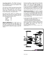
Page 14: ...he slider worksection s spool of the tailgate mounted valve Spec is 2750 PSI 50 PSI throttle advanced This device is very fast acting and can not be measured with a common glycerin filled gauge A glycerin filled gauge will give a reading that is very false SECONDARY PORT RELIEF This cartridge type port relief is screwed into the sweep worksection on the cylinder s base end of the tailgate mounted ...

Page 15: ...ith a 2 1 2 rod diameter These are internally cushioned to reduce end of stroke pounding Premium quality design and manufacture by PETTIBONE TAILGATE CYLINDERS A pair of rod type hydraulic cylinders The EXCEL uses a 4 1 2 bore x 30 1 8 stroke with a 3 3 4 rod diameter These cylinders are single acting since the EXCEL has a gravity lowered tailgate These have integral port mounted orifices IN CAB R...

Page 16: ...VING HOPPER BLADES AND THE HOPPER LOADING SILL WHEN BLADES ARE MOVING IF YOU OR A WORK PARTNER IS CAUGHT IN THE BLADE ACTION SERIOUS INJURY OR DEATH WILL RESULT To adjust the cycle time alter the diesel s throttle advanced RPM setting Do not adjust outside the previously specified range damage to componentry may occur Most diesels today are E DIESELS You will most likely need to schedule a visit t...

Page 17: ...gn on the steering wheel that says DO NOT START 2 Open body side access door and enter the body 3 Remove the acorn nut which acts as a cover over the adjuster stem 4 Loosen ccw the jambing nut 5 Use a hex key to turn the adjuster start with about 1 8 turn Turning adjuster inward cw will increase the setting Turning the adjuster outward ccw will decrease the setting 6 Tighten jamb nut and install a...

Page 18: ... is still soaking 7 Begin slowly turning upward cw the main relief s hex key adjuster slowly and smoothly All the while keep your eyes affixed upon the gauge Soon you will feel and hear the slider s knock out kick to neutral Memorize and jot down on paper the gauge reading that occurred at the very moment it kicked out This is the present slider k o setting 8 Repeat steps 3 7 again until you have ...

Page 19: ...to first correctly identify the one you choose to work on The slider k o is the lowest one nearest to the hopper s loading sill the slider work section has the switch trigger on its push pull rod DANGER Be sure diesel is not running keys are in your pocket and affix a sign on steering wheel that reads do not start before you enter the hopper or get near the hopper s blades Repeat these lockout tag...

Page 20: ...culprit and the cartridge and its setting are actually fine A typical symptom that might lead you to replace this cartridge is that the sweep blade is tending to unwrap when the body is nearing its full rated payload capacity Be careful in your observations here because some occasional unwrap of sweep blade is normal such as when the body really is full and the payload is at its rated value One wo...

Page 21: ...dy the schematics in this manual Also it is good practice to CHECK the condition of the Synkpaks two cartridge SEALS first then do the adjustment If seals show any evidence of erosion then replace with the urethane seals seal kit p n 8800717 march2004 Any failed cartridge seal will most likely make the synkpak malfunction two seals per cartridge two cartridges 4 seals to check To check the conditi...

Page 22: ...es have labels printed on them A fuse can appear good but is actually open If it is cooked open then you will have to replace it and consider why the fuse blew in the first place There may be a short that needs fixing Try to advance the throttle with one of the two manual button switches If throttle does not advance from one of these button switches then the problem is possibly an open circuit lik...

Page 23: ...led condition can cause suction line vortexing which entrains huge amounts of air The hydraulic fluid itself should not be milky which means water is contaminating the oil The suction strainer in the tank at the very bottom may be plugged with contaminants or a shop rag and its built in bypass is stuck closed rare Be certain the pump s suction line is not allowing air to be sucked rare re tighten ...

Page 24: ... observe that it operates normal The knockouts should knockout cleanly and consistently at full cylinder strokes The knockouts should hold the hand levers spools fully shifted during blade movements Stopwatch the blade cycle time see Table of Contents for correct procedure The advanced RPM may be way below spec and this takes the pressures down with it Listen to the hydraulics as you cycle blades ...

Page 25: ...t the tie bolts that hold the stack up of GRESEN V40 sections are over torqued or unevenly torqued Re torque these evenly to 26 ft lbs TAILGATE WILL NOT RAISE OR ONLY PARTILALLY RAISES The only pressure control device for the tailgate is the main relief valve of the body mounted valve First do a main relief check and setup See Table of Contents for this procedure The EXCEL s main relief is properl...

Page 26: ...foot throttle to increase diesel speed to about 1200 RPM for another couple of minutes 10 Cycle any optional equipment the vehicle may have such as the kickbar option about 3 times Then do a hopper blades semi automatic cycles a couple of times 11 Do a tank fill level check and top off See Table of Contents for proper way to check tank s level 12 If the old pump failed catastrophically change out ...

Page 27: ...moving any port mounted anticavitation check or port relief position the blades so it will not move by gravity when you remove the cartridge The slide blade must be fully down The sweep blade must dangle nearly vertical so gravity will not move it REMOVING THE CARTRIDGE WILL UNBLOCK THE PORT IT APPLIES TO You may want to temporarily weld some steel scrap between a blade and the tailgate s shell Di...

Page 28: ...so you can replumb exactly as it was 4 Before doing the actual valve disassembly study the valve and label or number sections so you can reassemble it the same as it was 5 Remove three assembly stud tie bolt nuts Do not remove the tie bolts 6 Remove the sections from tie rod bolts by sliding them to get at the one you are interested in 7 Thoroughly clean o ring counterbores and ground surfaces of ...

Page 29: ... RECONNECTING THE VEHICLE S BATTERIES Disconnect the truck s batteries before doing any welding to the EXCEL If the batteries are left connected during welding the vehicles charging system will be damaged alternator regulator Most truck chassis today have computers on board that could also be damaged if the battery cables and any harness connectors are left connected during welding When you remove...

Page 30: ...satisfy this requirement It is critical that it be understood that all three of the above support methods be provided Using just two of them is NOT sufficient Just after the tailgate is secured in three ways in this position the next step is to do your shop s detailed LOCKOUT TAGOUT procedure Always shutdown the diesel and place the ignition keys in your pocket before going underneath the securely...

Page 31: ...ir storage pockets do not stand underneath the raised tailgate stand off to the vehicle s side 13 Now fully lower and latch the tailgate Before lowering the gate be certain that no person is underneath the tailgate LOADMASTER recommends that one person stand well off to the side of the gate watching the pinch point between the gate and the body while a second person at the tailgate raise lower han...

Page 32: ... cable length adjustment for the 2 10 option The chart below shows the proper technique for anchoring The 2 10 uses diameter cable KEEP THE CLIP CLOSEST TO THE LOOP S THIMBLE AS CLOSE TO THIMBLE AS IS PRACTICAL INSPECT THE CABLE S CONDITION AND CABLE S ROOF TOP CABLE ANCHOR AT LEAST WEEKLY Sec04 pg07 Loadmaster uses dia ...

Page 33: ...Sec07 pg18 blank for notes ...

Page 34: ...Hydraulics Schematic XL TYPICAL LEFT HALVE june 09 REV ...

Page 35: ...Hydraulics Schematic XL TYPICAL RIGHT HALVE june 09 REV ...

Page 36: ...Electrical Schematic Chassis Interfacing Generic Diagram LoadMaster will record each Chassis Interface on this Schematic this CHASSIS TO L M BODY hard wiring Varies per chassis diesel transm pump etc ...

Page 37: ...Electrical Schematic BLANK ...

Page 38: ...Electrical Schematic OVERALL GENERIC left Halve ...

Page 39: ...Electrical Schematic OVERALL GENERIC right Halve ...

Reviews: