Note
: Use These Instructions for
Standard
Installations
Step Five: Connect to Telephone
Telephone Line in Place
If there is still a conventional PSTN line in place with a dial tone then follow the
instructions below. If there is no PSTN line with a dial tone in place, follow the
instructions for “No Telephone Line.”
Note:
A VoIP system may provide dial tone to the alarm panel jack. If this
is the case, a telephone connection may be made to this line following the
“Recommended Method” below. However, the system will be unreliable
when used as backup for PSTN calls from the alarm panel.
There are two methods of connecting the LNI 2000 to telephone service;
Using RJ45 plugs (recommended), or
Hardwiring.
Using a RJ45 plug to make the telephone connection avoids the additional step
of removing the terminal strip cover, while ensuring a firm and reliable
connection.
Recommended Method: RJ45 connection
1.
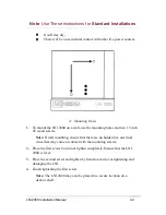
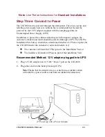
Unplug the existing alarm cable from the RJ31X (CA38A) jack, leaving the
other end connected (wired) to the alarm panel.
2.
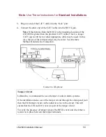
Connect the disconnected cable to the LNI 2000 by plugging it into the
“Panel” port.
Note:
If the distance from the alarm panel to the mounting location
of the LNI 2000 is greater than the existing alarm cable, fashion a
new cable from a CAT 5 or other appropriate 4-conductor cable. In
this case, the use of the terminal strips may be easier. See Alternate
Method: Hardwire the Connection.
LNI 2000 Installation Manual
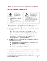
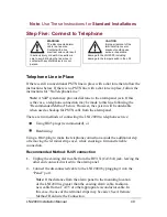
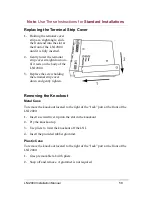
CAUTION
Improper removal of the
terminal strip cover or
knockout could cause
serious, irreparable
damage to the LNI 2000, including
damage to the tamper switch in the LNI.
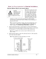
WARNING
The disconnected alarm
cable is a live wire.
Contact with a live
electrical wire could result
In serious injury or death. Use extreme
care to avoid bringing the live wires in
contact with any metal objects or your
person.
49

