The combustion air inlet pipe is a dedicated
system with one air inlet pipe per unit. The air
inlet pipe must be connected to the Direct Vent
(DV) box adapter. The air inlet pipe must be
sealed.
Aire-Lock
TM
Horizontal Direct Vent Kits
The vent kit includes a DV box adapter; sidewall
air inlet cap and sidewall vent termination.
Lochinvar must furnish this vent kit in accordance
with CSA International requirements.
Vertical Direct Vent Termination
You must use the vent termination
recommended by the vent manufacturer for
vertical direct vent terminations.
The installer supplies all vent pipe
material.
The combustion air inlet cap
must
be
installed at least 1 foot (0.30m) above
ground level and above normal snow levels.
The point of termination for the combustion air
inlet cap
must
be at least 3 feet (0.91m)
below the point of flue gas termination if it is
located within 10 feet (3.05m) of the flue outlet.
The combustion air inlet cap
must
not be
installed closer than 10 feet (3.05m) from an
inside corner of an L-shaped structure.
Both the combustion air inlet cap and the flue
gas vent termination
must
be installed in the
same pressure zone.
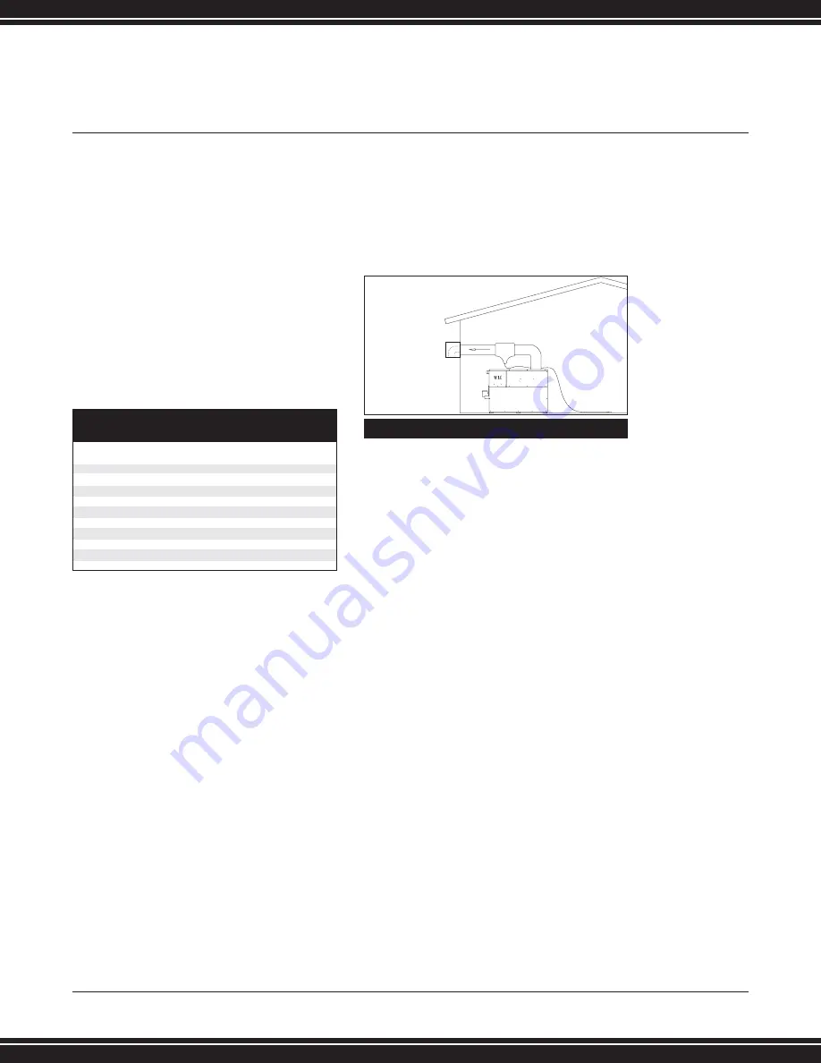
Sidewall Vent
This vent system utilizes the internal blower of
the unit to vent the by-products of combustion
to the outdoors. This vent system requires the
installation of one pipe for flue products. The
vent pipes terminates horizontally at a
sidewall. The vent system has specific vent
material and installation requirements. The
vent piping for flue products uses AL29-4C
vent material and must be sealed "gastight"
at all vent joints. The vent connection is made
directly to the top of the unit. The maximum
distance for the flue pipe is 50 equivalent feet
(15.2m). Subtract 5 feet (1.52m) for each
elbow in the flue pipe. The flue products vent
pipe is a dedicated system with one flue pipe
per unit.
Sidewall Vent Kits
The vent kit includes a sidewall vent
termination assembly to provide pressure
equalization. Lochinvar must furnish this
vent kit in accordance with CSA
International requirements.
L o c h i n v a r
D E S I G N E R
’
S
G U I D E
C O P P E R
-
F I N
I I
W A T E R
H E A T E R
6 1 5 - 8 8 9 - 8 9 0 0
1 5
(TABLE G)
AIRE-LOCK DIRECT VENT KIT PART NUMBERS
MODEL
FLUE
AIR
PART
NUMBER
SIZE
INLET SIZE
NUMBER
CF401
6
”
6
”
DVK3004
CF501
6
”
6
”
DVK3004
CF651
8
”
8
”
DVK3005
CF751
8
”
8
”
DVK3005
CF991
10
”
10
”
DVK3000
CF1261
12
”
12
”
DVK3001
CF1441
12
”
12
”
DVK3001
CF1801
14
”
12
”
DVK3002
CF2071
14
”
12
”
DVK3002
(FIG. 15) SIDEWALL VENT


