60
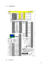
16.5
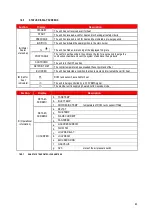
STATUS DISPLAY SCREENS
Section
Display
Description
A (Water
heater
status bar)
STANDBY
The unit has not received a call for heat
START
The unit has received a call for heat and is checking all safety circuits
PREPURGE
The unit has received a call for heat and has initiated a pre-purge period
IGNITION
The unit has initiated the spark ignition to the main burner
%
The unit has fired and is running at the displayed firing rate
POSTPURGE
The call for heat has ended, the unit runs the fan for a set period to purge the
combustion chamber and vent the system of additional flue products
SHUTDOWN
The unit is in the OFF position
SETPOINT MET
The control temperature has exceeded the set point and offset
BLOCKED
The unit has detected a condition that has temporarily interrupted the call for heat
B (Call for
heat
indicators)
DHW tank sensor has called for heat
The unit is being controlled by a 0-10V BMS signal
The member unit is supplying heat whilst in Cascade mode
Section
Display
Description
C (Operational
information)
DETAILS
SCREEN 1
b.
TANK TEMP
d.
INLET TEMP
f.
DHW RECIRC TEMP
temperature of DHW recirc sensor if fitted
DETAILS
SCREEN 2
a.
DELTA T
b.
FLUE TEMP
c.
FLAME CURRENT
d.
FAN SPEED
I/O SCREEN
a.
GAS PRESSURE SW
b.
FLOW SW
c.
LOUVRE RELAY
d.
LOUVRE SW
e.
BLOCKED DRAIN
f.
GAS VALVE
g.
APS
state of the air pressure switch
16.5.1
SMART
SYSTEM
CONTROL
PARAMETERS
Summary of Contents for ECOKNIGHT EKW116CE
Page 28: ...28 Max distance between brackets ...
Page 29: ...29 ...
Page 30: ...30 ...
Page 34: ...34 ...
Page 35: ...35 ...
Page 55: ...55 15 8 WIRING DIAGRAM 15 8 1 WIRING DIAGRAM ...
Page 56: ...56 15 9 LADDER DIAGRAM 15 9 1 LADDER DIAGRAM ...
Page 87: ...87 ...
Page 88: ...88 ...

