43
13.1
VESSEL TEMPERATURE SENSOR SINGLE WATER HEATER INSTALLATION
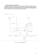
Each EcoKnight™ is supplied with a vessel temperature sensor and sensor pocket. This must be fitted to the LST direct storage
vessel supplied with the EcoKnight™ water heater.
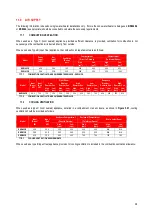
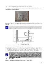
This is installed within the vessel as close to the flow and return connections as possible depending upon vessel chosen see diagram
13.1.1. Point 7
On systems with multiple storage vessels it is recommend that the water heaters only read the
temperature of a single vessel, the vessels should be balanced so they are all the same temperature.
13.1.1
TYPICAL
LST
CONNECTION
POINTS
1.1
VESSEL TEMPERATURE SENSOR MULTIPLE WATER HEATER INSTALLATION
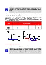
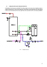
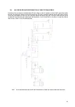
When installing multiple water heaters it is recommended that the water heaters are installed using the cascade management system,
see section 21.6. When in cascade only the lead water heater and alternate lead have tank sensors fitted see 1.1.1. The lead water
heater will monitor the tank temperature and control the water heaters within the cascade, in the event of a failure of the lead water
heater then the alternate leader will take over control of the system, hence it is also required to have a tank sensor fitted.
It may not be possible to fit two sensors into a single tank when using a cascade system with lead/alternate
lead. If there are two tanks then the alternate lead can have its sensor placed in the second tank see 14.4.1,
due to the fact the vessels should be balanced then the temperature will be the same in both tanks. If the
system only has a single tank then the alternate lead will need to use a strap on sensor located onto the
pipework near to the tank see 14.2.1 – this is less accurate but will allow the system to continue operating
whilst the lead water heater is repaired.
13.2
SENSOR WIRING
For guidance on installing the wiring for the temperature sensor, please refer to Section: 15.4.1
Summary of Contents for ECOKNIGHT EKW116CE
Page 28: ...28 Max distance between brackets ...
Page 29: ...29 ...
Page 30: ...30 ...
Page 34: ...34 ...
Page 35: ...35 ...
Page 55: ...55 15 8 WIRING DIAGRAM 15 8 1 WIRING DIAGRAM ...
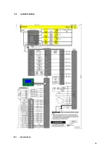
Page 56: ...56 15 9 LADDER DIAGRAM 15 9 1 LADDER DIAGRAM ...
Page 87: ...87 ...
Page 88: ...88 ...


