78
21.6.10
ALTERNATE
LEADER
This parameter allows the Member 1 water heater to automatically assume control of the Cascade should it lose communication
with the Leader water heater. When programmed to YES, it is recommended that the Member 1 water heater have its own set of
external sensors installed (such as the Vessel sensor), to maintain the same level of temperature control as with the Leader water
heater. Voltage signals (such as the 0 - 10V system pump speed input) can be connected to both water heaters.
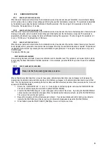
Do not connect the sensors connected to the leader water heater to the member 1 water heater. The actual
water temperatures will be higher than expected, which could lead to property damage or personal injury.
When communication is re-established with the Leader water heater, Member 1 will automatically relinquish control of the Cascade
to the Leader water heater.
The default value of this parameter is NO.
21.6.11
WATER
HEATER
SIZE
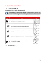
When water heaters of different sizes are connected together in a Cascade, the Leader water heater has to know the size of each
water heater in that Cascade. The Water Heater Size parameters allow the installer to program the size based on the Cascade
address. This screen shows the Cascade address and the size of the water heater with that address (in kBtu/hr):
1.
When the water heater size screen is first accessed, Cascade Address (SELF) is shown.
2.
Press the NAVIGATION dial twice to access the Input setting. Rotate the NAVIGATION dial to increase the boiler
input. Input settings 0 - 400 Btu/hr can be adjusted in increments of 5 (5000 Btu/hr). When the closest approximate
boiler size is shown, press the RIGHT SELECT [SAVE] key.
3.
Rotate the NAVIGATION dial to select the address of the next water heater in the Cascade. Repeat Step two above.
4.
Once the size of the last water heater in the Cascade has been entered and saved, press the LEFT SELECT [EXIT] key
to return to the Control Modes menu.
5.
If no other parameters are to be adjusted, press the RIGHT SELECT [HOME] key to save the new settings and return to
the Status screens.
The SMART SYSTEM control automatically uses the Efficiency Optimisation Cascade type when controlling water heaters of
different sizes.
21.7
BUILDING MANAGEMENT SYSTEM (BMS)
21.7.1
BMS
The set point or modulation of the water heater may be controlled through the 0 - 10V BMS input, BACnet, or ModBus. When the
BMS parameter is set to INACTIVE, the 0 - 10V input will be ignored. When set to ACTIVE, the set point or modulation will be
controlled by the voltage on the 0 - 10V input (in the case of 0 - 10V BMS control), or the 0 - 10V input value received through
ModBus or BACnet. The default value is INACTIVE.
21.7.2
BMS
TYPE
When programmed for BMS control through the 0 - 10V BMS input or through ModBus/BACnet, the 0 - 10V signal can be
interpreted as either a modulation command or a set point. When the BMS Type parameter is set to POWER, the 0 - 10V signal
will control the modulation. When set to SETPOINT, the 0 - 10V signal will control the SH set point. The default setting is
SETPOINT.
21.7.3
RATE
AT
MINIMUM
VOLTS
When programmed for BMS control through the 0 - 10V BMS input or through ModBus/BACnet and the BMS Type is
programmed as POWER, the modulation percentage represented by the Volts at Minimum parameter is set by the Rate at
Minimum Volts parameter. The minimum value is 0% and the maximum is the Rate at Maximum Volts setting. The default value
is model dependant.
21.7.4
RATE
AT
MAXIMUM
VOLTS
When programmed for BMS control through the 0 - 10V BMS input or through ModBus/BACnet and the BMS Type is
programmed as POWER, the modulation percentage represented by the Volts at Maximum parameter is set by the Rate at
Maximum Volts parameter. The minimum value is the Rate at Minimum Volts setting and the maximum is 100%. The default value
is 100%.
21.7.5
SET
POINT
AT
MINIMUM
VOLTS
When programmed for BMS control through the 0 - 10V BMS input or through ModBus/BACnet and the BMS Type is programmed
as SETPOINT, the set point represented by the Volts at Minimum parameter is set by the Set Point at Minimum Volts parameter.
The minimum value is 32°F (0°C) and the maximum is the Set Point at Maximum Volts setting. The default value is 70°F (21°C).
Summary of Contents for ECOKNIGHT EKW116CE
Page 28: ...28 Max distance between brackets ...
Page 29: ...29 ...
Page 30: ...30 ...
Page 34: ...34 ...
Page 35: ...35 ...
Page 55: ...55 15 8 WIRING DIAGRAM 15 8 1 WIRING DIAGRAM ...
Page 56: ...56 15 9 LADDER DIAGRAM 15 9 1 LADDER DIAGRAM ...
Page 87: ...87 ...
Page 88: ...88 ...


