18
10.2
FLUE DISCHARGE
The flue system must ensure safe and efficient operation of the equipment to which it is attached, protect the combustion process from wind
effects and disperse the products of combustion to open external air.
The flue must terminate in a freely exposed position and be so situated as to prevent the products of combustion entering any opening in a
building. For installations with a total output above 333kW nett, the clean air act should be consulted and complied with.
Under certain operating and weather conditions, the EcoShield™ water heater may generate a plume at the terminal. Consideration should be
given to the nuisance this may cause and the terminal should be sited accordingly.
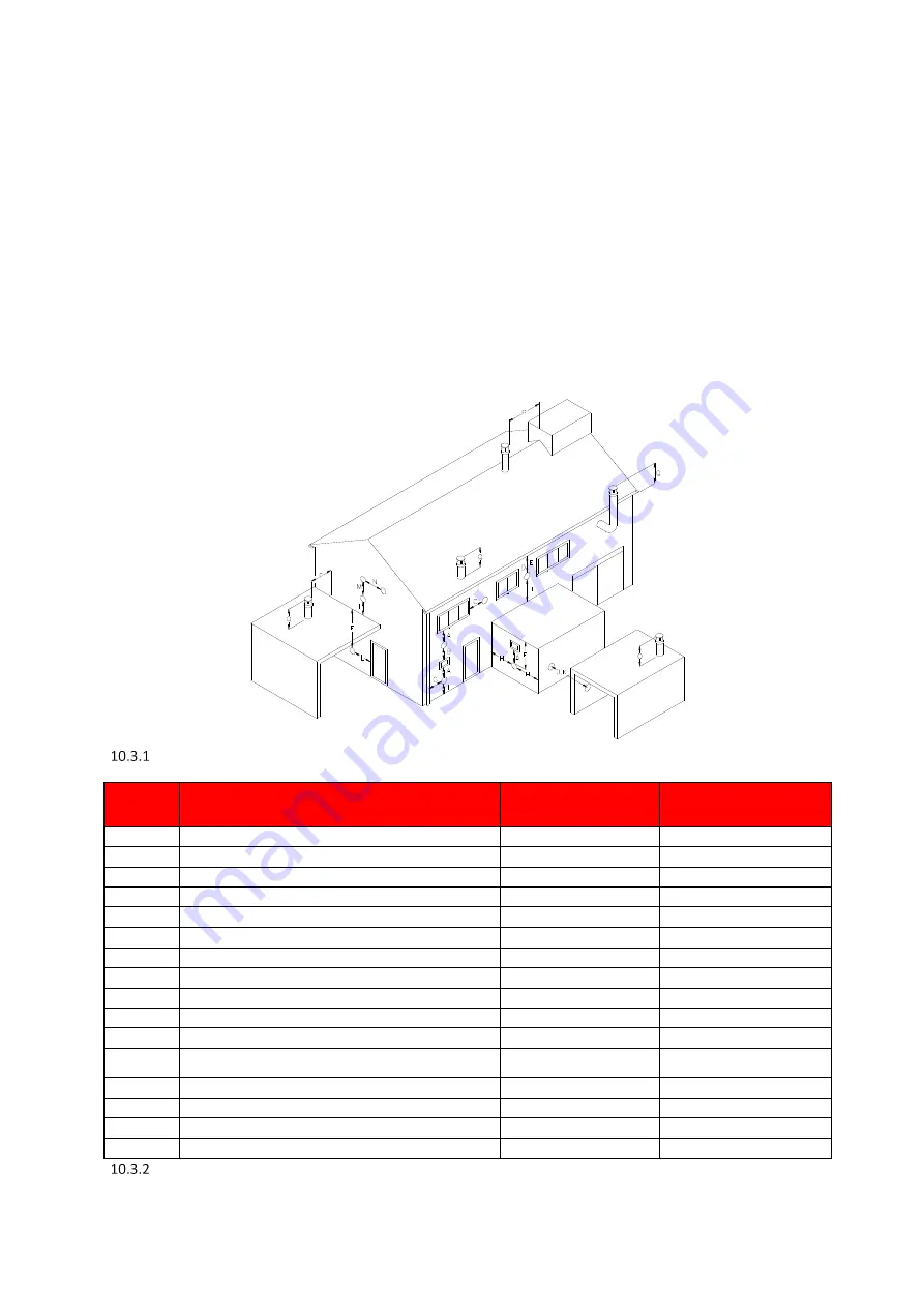
For further information on terminal locations, please refer to Section 10.3.1 FLUE TERMINAL POSITIONS.
10.3
CONDENSATE DRAIN
If the flue system rises at an angle of at least 3
(50mm per metre), no additional condensate drain will be required. Failure to provide an
adequate rise in the flue system may lead to pooling of condensate which may lead to premature failure of the flue system.
FLUE
TERMINAL
POSITIONS
Location
Description
SHW35-245CE
SHW46-325CE
SHW61-325CE
SHW86-410CE
SHW116-410CE
SHW146-410CE
A
Directly below an opening, air brick, opening windows etc.
300
2000
B
Above an opening, air brick, opening windows etc.
300
1000
C
Horizontally to an opening, air brick, opening windows etc.
300
1000
D
Below a gutter or sanitary pipework
75
75
E
Below the eaves
200
200
F
Below a balcony or car port roof
200
200
G
From a vertical drain or soil pipe
150
150
H
From an internal or external corner
300
300
I
Above ground, roof or balcony level
300
300
J
From a surface facing the terminal
600
1000
K
From a terminal facing the terminal
1200
2000
L
From an opening in the car port (e.g. door, window) into the
dwelling
1200
1200
M
Vertically from a terminal on the same wall
1500
1500
N
Horizontally from a terminal on the same wall
300
600
P
From a vertical structure on the roof
300
300
Q
Above intersection with the roof
300
300
FLUE
TERMINAL
MINIMUM
DISTANCES
Summary of Contents for EcoShield SHW116-410CE
Page 2: ...2 ...
Page 9: ...9 EXPLODED VIEW DRAWINGS ...
Page 27: ...27 Max distance between brackets ...
Page 28: ...28 ...
Page 29: ...29 ...
Page 34: ...34 ...
Page 47: ...47 13 9 LADDER DIAGRAM LADDER DIAGRAM ...
Page 71: ...71 NOTES ...
Page 72: ...72 N ...


