background image


48 

14.0


USER CONTROL INTERFACE 

 
14.1


GENERAL 


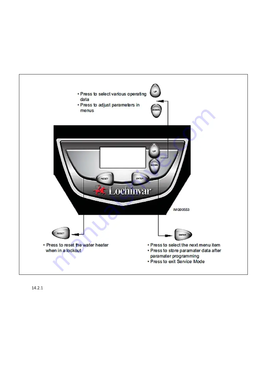
The EcoShield™ user control interface gives information on set-up, system status and diagnostic data. 
 

14.2


USER CONTROL INTERFACE PANEL 


USER


CONTROL


INTERFACE


PANEL 

Summary of Contents for EcoShield SHW116-410CE

Page 1: ...tion Manual_EcoShield_October 2018 EcoShield Gas Fired Condensing Water Heaters MODELS SHW35 245CE SHW46 325CE SHW61 325CE SHW86 410CE SHW116 410CE SHW146 410CE Installation Commissioning Maintenance instructions ...

Page 2: ...2 ...

Page 3: ...FLUE SYSTEMS IN MULTI FLOOR BUILDINGS 30 10 16 C53 TWIN PIPE FLUE SYSTEMS 31 10 17 FLUE TERMINAL GUARDING 35 10 18 TYPE B23 CONVENTIONAL FLUE WITH FAN ASSISTANCE 36 10 19 C63 CERTIFIED FLUE SYSTEMS 37 11 0 AIR SUPPLY 38 11 1 COMBUSTION VENTILATION 38 11 2 COOLING VENTILATION 38 12 0 WATER CONNECTIONS 39 12 1 GENERAL 39 12 2 OPEN VENTED SYSTEM ARRANGEMENT 39 12 3 UNVENTED SYSTEM ARRANGEMENT 40 13 0...

Page 4: ...USTABLE PARAMETERS SCREEN 62 18 4 PASTEURISATION FUNCTION USING NIGHT SET BACK FACILITY 63 18 5 NIGHT SETBACK SCREEN 65 18 6 SERVICE MODE SCREEN 65 18 7 ERROR LOG SCREEN 65 19 0 TROUBLESHOOTING 66 19 1 CHECKING TEMPERATURE SENSORS 66 19 2 TROUBLESHOOTING CHART 66 19 3 ERROR CODES 67 20 0 ErP SPECIFICATION DATA SHEET 70 21 0 USER INSTRUCTIONS 70 ...

Page 5: ...e on Group H Natural Gas 2nd Family and LPG propane 3rd Family The information relating to propane firing is to be found in Section 16 0 LPG FUEL This equipment MUST NOT use gas other than that for which it has been designed and adjusted This equipment must be installed by a competent person registered with a HSE approved body All installations must conform to the relevant Gas Safety and Building ...

Page 6: ...er certification becomes invalid Commissioning maintenance and repair must be done by a skilled installer engineer according to all applicable standards and regulations 2 1 GENERAL DESCRIPTION OF SAFETY SYMBOLS USED BANNED A black symbol inside a red circle with a red diagonal indicates an action that should not be performed WARNING A black symbol added to a yellow triangle with black edges indica...

Page 7: ...to do so Lochinvar Limited is not liable for any damage caused by inaccurately following these installation instructions Only original parts may be used when carrying out any repair or service work This appliance is not intended for use by persons including children with reduced physical sensory or mental capabilities or lack of experience and knowledge unless they have been given supervision or i...

Page 8: ...UE TEMPERATURE SENSOR GROMMET N A MSC2200 12 FAN ASSEMBLY FAN2050 FAN2051 FAN2052 FAN2053 FAN2054 FAN2055 13 FAN GASKET GKT2456 GKT2436 GKT2456 GKT2436 14 FLUE TEMPERATURE SENSOR TST20007 TST30011 15 GAS VALVE ASSEMBLY VAL30071 VAL30072 VAL30073 VAL30074 VAL30075 VAL30076 16 IGNITION CABLE WRE2209 17 IGNITION ELECTRODE C W GASKET PLT3021 18 INLET TEMPERATURE SENSOR TST20037 19 OUTLET TEMPERATURE S...

Page 9: ...9 EXPLODED VIEW DRAWINGS ...

Page 10: ...t pressure mbar 20 Maximum gas inlet pressure mbar 25 Minimum gas inlet pressure mbar 17 5 Gas flow rate m3 hr 3 5 4 2 5 7 8 11 1 14 Flue gas mass rate 9 0 CO2 g sec 13 6 16 22 3 30 4 42 5 53 2 Gas inlet connection size B S P 1 1 GAS DATA G31 Nominal gas inlet pressure mbar 37 Maximum gas inlet pressure mbar 45 Minimum gas inlet pressure mbar 27 Gas flow rate m3 hr 1 4 1 7 2 3 3 1 4 4 5 5 Flue gas...

Page 11: ...E COLD FEED HOT OUTLET A B C D E SHW35 245 244 1530 715 755 1610 1610 SHW46 325 325 1920 715 1117 2005 2005 SHW61 325 325 1920 715 1126 2005 2005 SHW86 410 410 1920 865 786 2020 2020 SHW116 410 410 1920 865 786 2020 2020 SHW146 410 410 1920 865 786 2020 2020 DIMENSIONAL DRAWING ECOSHIELD ...

Page 12: ...nd each unit This includes any electrical trunking laid across the floor and to the appliance RECOMMENDED SERVICE CLEARANCES TOP 450mm LEFT 600mm RIGHT 100mm FRONT 600mm REAR ZERO FLUE 25mm ENCLOSURE INSTALLATION CLEARANCES MM RECOMMENDED SERVICE CLEARANCES TOP 450mm LEFT 600mm RIGHT 100mm FRONT 600mm REAR ZERO FLUE 25mm PLANT ROOM INSTALLATION CLEARANCES MM Further details regarding locations are...

Page 13: ...and maintenance of flues and ventilation for gas appliances of rated input not exceeding 70 kW net 1st 2nd and 3rd family gases Specification for installation and maintenance of ventilation for gas appliances BS 6644 2011 Specification for Installation of gas fired hot water Heaters of rated inputs between 70 kW net and 1 8 MW net 2nd and 3rd family gases BS EN 806 1 5 Specifications for installat...

Page 14: ...tilation for cooling and combustion must be provided For further details please refer to Section 9 AIR SUPPLY or to BS5440 2 or BS6644 as appropriate 8 2 GENERAL REQUIREMENTS Corrosion of the heat exchanger and flue system may occur if air for combustion contains certain chemical vapours Such corrosion may result in poor combustion and create a risk of asphyxiation Aerosol propellants cleaning sol...

Page 15: ...PG pipework installation guidance 9 4 BOOSTED SUPPLIES Where it is necessary to employ a gas pressure booster the controls must include a low pressure cut off switch at the booster inlet The local gas distributor must be consulted before a gas pressure booster is fitted For details of how to connect a low pressure cut off switch please refer to Section 11 Electrical Supply 9 5 PLANT ROOM CONTROL V...

Page 16: ...he possible risk of ice building up on surrounding parts structures because the condensate will freeze This risk should be taken into account during the design phase of the heating installation EcoShield Water heaters will produce large condense clouds especially during cold weather consideration must be taken as to whether this will cause a nuisance to neighbouring properties and if so alternativ...

Page 17: ...E DATA TYPE C43 C53 Nominal flue diameter dnom mm 80 100 Nominal flue diameter doutside mm 80 0 3 100 0 3 Nominal flue diameter dinside mm 81 0 6 101 0 6 Nominal flue diameter Linsert mm 50 20 2 50 20 2 Minimum flue gas temp C 35 Average flue gas temp C 70 Maximum flue gas temp C 120 Maximum equivalent length m 60 Equivalent length 90 bend mm 1000 Equivalent length 45 bend mm 500 FLUE DATA TYPE C6...

Page 18: ...will be required Failure to provide an adequate rise in the flue system may lead to pooling of condensate which may lead to premature failure of the flue system FLUE TERMINAL POSITIONS Location Description SHW35 245CE SHW46 325CE SHW61 325CE SHW86 410CE SHW116 410CE SHW146 410CE A Directly below an opening air brick opening windows etc 300 2000 B Above an opening air brick opening windows etc 300 ...

Page 19: ...water heater connections concentric adaptor if required flue pipes air ducts if required and terminals If discharging at low level a suitable flue guard must be installed During assembly precaution should be taken to ensure that the internal sealing ring is seated correctly Due to the close tolerances in the flue system it may be necessary to use a twisting action to fit the joints together No lub...

Page 20: ...3 Vertical Concentric flue the flue transition kit should be installed to the top of the heater as per 10 9 3 and 10 9 7 SHW35 245 SHW46 325 SHW61 325 SHW86 410 SHW116 410 SHW146 410 ECOSHIELD SHOWING TRANSITION KIT FITTED TRANSITION KIT SHW35 245CE SHW61 325CE FLUE TRANSITION DETAILS SHW35 245CE SHW61 325CE ...

Page 21: ...n reducer and tighten the worm drive clip 2 Fit 80mm elbow Item 3 in Table to cut end of extension 3 To the side intake connection of the concentric adaptor Item 1 in Table fit the other end of the 80mm dia Extension 4 Fit the bottom flue connection of the concentric adapter to the flue connection on the heater TRANSITION KIT SHW86 410CE SHW116 410CE SHW146 410CE FLUE TRANSITION DETAILS SHW86 410C...

Page 22: ...rizontal flue kit includes the items shown in the tables below Item No SHHF003 CONCENTRIC HORIZONTAL FLUE ASSEMBLY MODELS SHW35 245 SHW46 325 SHW61 325 COMPONENTS INCLUDED Item No Description Included M86934 CONCENTRIC HORIZONTAL TERM Ø80 125mm PP NO WALL PLATES 1 M28925 TERMINAL WALL PLATES PAIR 1 M121602 TWIN PIPE TO CONCENTRIC ADAPTOR Ø80 80mm TO Ø80 125mm PP 1 M75256 AIR INLET TRANSITION Ø80mm...

Page 23: ...e outer wall plate or rosette should be flush to the wall see 10 11 1 Once cut remove all burrs and sharp edges 4 Insert the terminal into the drilled hole The terminal section should be installed level or with a fall to outside Max 10mm per metre to prevent the ingress of water When inserting the terminal ensure the air intake section is at the bottom 5 Fill the void between the terminal and wall...

Page 24: ...50mm PP 1 LV310754 CONCENTRIC VERTICAL TERMINAL Ø100 150mm PP 1 10 14 VERTICAL FLUE TERMINAL INSTALLATION When the water heater is installed as a Type C33 appliance the flue system should be installed as follows 1 Confirm that the roof flashing is correct for the type of roof through which the terminal is to be installed Section 10 14 1 2 Determine the desired location for the flue terminal taking...

Page 25: ...ecure using appropriate fixings Do not tighten the support bracket 8 Install the remainder of the flue system working progressively away from the water heater supporting the pipes as necessary 9 Once the flue system is fully installed tighten the clamp to secure the terminal in place VERTICAL TERMINAL ROOF FLASHINGS FOR SYNTHETIC FLAT AND TILED ROOFS INSTALLING TERMINAL THROUGH ROOF FLASHING ...

Page 26: ...NERAL CONCENTRIC FLUE SYSTEM INSTALLATION GUIDELINES The information in this section is for General guidance only and may not fully represent the installation on site Do not drill and screw into flue system ...

Page 27: ...27 Max distance between brackets ...

Page 28: ...28 ...

Page 29: ...29 ...

Page 30: ...aught chimney The common duct is part of the building not a part of the system CONDENSATE DRAIN Condensate can flow back to the appliance this will travel through the heat exchanger into the condensate drain via the trap If the flue system rises at an angle of at least 3 50mm per metre no additional condensate drain will be required Failure to provide an adequate rise in the flue system may lead t...

Page 31: ...IZONTAL AIR INLET Ø80mm HORIZONTAL FLUE M86934 CONCENTRIC HORIZONTAL TERMINAL Ø80 125mm PP NO WALL PLATES LV305016 HORIZONTAL AIR INLET Ø80mm M28925 TERMINAL WALL PLATES PAIR Item No SHTF004 TWIN PIPE FLUE STARTER ASSEMBLY MODELS SHW86 410 SHW116 410 SHW146 410 COMPONENTS INCLUDED WITHIN KIT TO START INSTALLATION Item No Description Included M75257 AIR INLET TRANSITION Ø100mm ALU 1 M85189 SAMPLING...

Page 32: ...nsor is not fitted the flue gas temperature may exceed the maximum temperature rating of the flue and can lead to severe personal injury death or substantial property damage To install a Type C53 terminal or air inlet the procedure for either a Type C13 horizontal or a Type C33 vertical terminal should be followed noting that the annular space of the terminal should be sealed off ...

Page 33: ...33 GENERAL TWIN PIPE INSTALLATION GUIDELINES The information in this section is for General guidance only and may not fully represent the installation on site ...

Page 34: ...34 ...

Page 35: ...e it can be touched from a window door or balcony a terminal guard must be fitted The terminal guard is constructed from plastic coated mild steel and is suitable for use on condensing appliances only The guard should be installed centrally around the terminal ensuring a gap of at least 50mm between the guard and terminal is maintained ...

Page 36: ...RILLE Ø80mm ALU 1 M85279 SAMPLING POINT Ø80mm PP 1 Item No SHCF004 CONVENTIONAL FLUE ASSEMBLY MODELS SHW86 410 SHW116 410 SHW146 410 COMPONENTS REQUIRED TO START INSTALLATION Item No Description Included M75257 AIR INLET TRANSITION Ø100mm ALU 1 M86787 APPLIANCE AIR INLET GUARD Ø100mm 1 M85189 SAMPLING POINT Ø100mm PP 1 The above is a kit of components to facilitate conventional flueing of the appl...

Page 37: ...5 1 101 0 5 150 1 0 5 50 20 2 When installing the water heater as a Type C63 appliance it should be noted that the terminals must not be installed on opposite sides of the building The maximum allowable recirculation rate is 10 under wind conditions Aluminium flue pipe must not be used on this appliance as it may lead to premature failure of the heat exchanger and will invalidate the warranty COND...

Page 38: ... Summer Use High Summer Use High cm2 Low cm2 High cm2 Low cm2 High cm2 Low cm2 High cm2 Low cm2 High cm2 Low cm2 High cm2 Low cm2 SHW86 410CE 83 5 75 3 152 304 228 380 304 456 380 760 456 836 532 912 SHW116 410CE 117 2 105 6 212 424 318 530 424 636 530 1060 636 1166 742 1272 SHW146 410CE 146 5 132 0 264 528 396 660 528 792 660 1320 792 1452 924 1584 COMBUSTION VENTILATION REQUIREMENTS SHW86 410CE ...

Page 39: ...uding the unit and any additional storage vessel 3 Tapping sizes for connection to the water system are detailed in 4 1 1Technical Data 4 Ideally individual valves should be fitted to each unit to enable isolation from the system The arrangement must comply with the requirements of BS6644 5 Typical pipework schematics are available from Lochinvar Limited upon request 12 2 OPEN VENTED SYSTEM ARRANG...

Page 40: ... system should follow the guidance given in BS6700 and must comply with the Building Regulations 1992 Part G3 in England and Wales P5 in Northern Ireland and P3 in Scotland A kit of components that have been suitably sized for the unvented operation of the appliance is available from Lochinvar Limited For further information contact Lochinvar Limited UN VENTED SYSTEM INSTALLATION SCHEMATIC ...

Page 41: ...ith a continuous fall d Have discharges visible at both the tundish and the final point of discharge but where this is not possible or is practically difficult there should be clear visibility at one or other of these locations Examples of acceptable discharge arrangements are I Ideally below the fixed grating and above the water seal in a trapped gulley II Downward discharges at a low level i e u...

Page 42: ...need to be made V V S V e 0 45 Where V V Vessel Volume S V System Volume e Coefficient of Expansion See Table 10 1 Stored Temp C 30 35 40 45 50 55 60 e 0 005 0 006 0 008 0 010 0 012 0 015 0 017 Stored Temp C 65 70 75 80 82 85 90 e 0 020 0 023 0 026 0 030 0 031 0 033 0 037 COEFFICIENT OF EXPANSION OF WATER AT 3 5 BAR INLET PRESSURE 13 0 ELECTRICAL SUPPLY Wiring external to the equipment must be ins...

Page 43: ...ee lock out alarm signal 24VAC auxiliary device enable signal e g to start fan dilution system REMOTE ENABLING When remote control of an EcoShield water heater is required and controlled using a Building Management System B M S the factory fitted ENABLE terminals wiring sensor should be interrupted using a suitable relay 13 3 MAINS POWER SUPPLY MAINS POWER SUPPLY TERMINAL CONNECTION NOTES MAINS Co...

Page 44: ...V COM RELAY Can be used to supply an enable signal to an external control such as a fan dilution system 7 8 RUNTIME CONTACTS An internal volt free contact across pins 7 8 will close in the event of the burner operating This connection can be used by a BMS to monitor the operation of the heater 9 10 ALARM CONTACTS An internal volt free contact across pins 9 10 will close in the event of the heater ...

Page 45: ...t is removed by mistake the resulting hole must be blocked with an appropriate anchor plug or grommet to prevent accidental access to the live parts within the water heater 13 6 FUSES The EcoShield has three internal fuses F1 will automatically reset F2 F3 are slow blow fuses located and rated as follows FUSE RATINGS AND LOCATIONS The water heater has three spare fuses in a plastic bag attached to...

Page 46: ... PR G G CAUTION HIGH VOLTAGE SPARK LEAD Notes 1 All wiring must be installed in accordance with I E E Regulations and any local regulations that apply 2 If any original equipment wire as supplied with the appliance must be replaced it must be replaced with wire having same wire gauge AWG and rated for a minimum of 105 C Exceptions Replacement high voltage spark lead and ribbon cables must be purch...

Page 47: ...47 13 9 LADDER DIAGRAM LADDER DIAGRAM ...

Page 48: ... 14 0 USER CONTROL INTERFACE 14 1 GENERAL The EcoShield user control interface gives information on set up system status and diagnostic data 14 2 USER CONTROL INTERFACE PANEL USER CONTROL INTERFACE PANEL ...

Page 49: ...h limit it must be closed before the control powers up the fan If there is a fan dilution device or similar connected to the unit the unit will provide 24 VAC to its enable relay If the fan dilution has a proving switch it must be closed before the sequence continues 3 The control starts a 10 second pre purge cycle 4 Once the pre purge cycle is complete and the blocked drain and auto reset high li...

Page 50: ...kout for 1 hour and then try another set of 4 trials On the SHW146 CE the unit will lockout until manually reset 6 If the control detects a flame before trial ignition ends it begins to modulate the burner in order to maintain the set point 7 Once the call for heat is satisfied the control will turn off the burner The fan will remain on for the 10 second post purge cycle The integrated pump will c...

Page 51: ...re that personnel involved are aware of what action is about to be taken and begin by making the following checks 1 Flue way passages are clear 2 Adequate ventilation exists in the plant room if necessary 3 The system is fully charged with water ready to receive heat All necessary valves are open and the building return pump if fitted is circulating water 4 The gas supply pipework is clear of any ...

Page 52: ... SHW86 410CE 8 8 0 5 100 ppm SHW116 410CE 8 8 0 5 100 ppm SHW146 410CE 8 8 0 5 100 ppm NATURAL GAS COMBUSTION FIGURES If the combustion figures are not within the range specified contact Lochinvar Technical support for further guidance Combustion figures for Propane firing can be found in Section 16 0 LPG FUEL 15 5 TEMPERATURE ADJUSTMENT PROCEDURE With the heater firing the set point can be adjust...

Page 53: ...inless steel or copper The operation of the EcoShield range on LPG Propane 3rd Family 3P is similar to that on Natural Gas 2nd Family 2H and the design and installation details described in the main body of the installer s guide should be followed 16 2 CONVERSION TO LPG This process must be carried out in the order stated before the water heater is switched on Failure to follow the following proce...

Page 54: ...wiring plug from the gas valve 3 Remove the three screws securing the venturi to the fan NOTE When separating the venturi from the fan take care not to damage the O ring inside the fan Figure 16 2 5 4 Remove the four cap head screws securing the gas valve to the venturi Figure 16 2 5 5 Locate the propane orifice disk from the conversion kit bag Verify that the stamping on the orifice disk is corre...

Page 55: ...Remove the existing orifice from the O ring in the side of the injector plate and replace it with the orifice from the kit Position and secure the orifice in the injector plate as shown in Figure 16 2 7 7 Reposition the manifold adapter to the injector plate and replace the four manifold adapter mounting screws Handle the O ring with care do not damage 8 Reposition the injector plate to the air sh...

Page 56: ...t gas air ratio inlet assembly This must not be tampered with Any attempt to adjust the gas valve or venturi will invalidate the warranty Combustion figures should be as follows Model No CO2 CO SHW35 245CE 10 5 0 5 100 ppm SHW46 325CE 10 5 0 5 100 ppm SHW61 325CE 10 5 0 5 100 ppm SHW86 410CE 10 5 0 5 100 ppm SHW116 410CE 10 5 0 5 100 ppm SHW146 410CE 10 5 0 5 100 ppm LPG COMBUSTION FIGURES If the ...

Page 57: ...mp up to full firing rate 3 Check the flame condition 4 Press the Enter button momentarily this should ramp the water heater down to low rate 5 Check the flame condition 6 Press and hold the Enter button for 5 seconds to take the unit out of service mode 17 3 BURNER REMOVAL If it has been determined that the flame picture is unacceptable the burner can be removed and cleaned using the following pr...

Page 58: ...s 8 Reinstall the burner 9 Restart the heater as detailed in Section 15 4 3 PROCEDURE FOR INITIAL LIGHTING 17 5 DRAINING THE WATER HEATER SYSTEM Maintenance and service procedures for the storage vessel require draining the water heater The water heater must also be drained if it is to be shut down and exposed to freezing temperatures 1 Turn off the water heater by pressing and holding the Up butt...

Page 59: ...e by more than 40 or if the surface is severely pitted the anode should be replaced Particular attention should be paid to the ends of each anode to ensure excessive localised depletion has not occurred 4 When refitting the inspected or replaced anode a suitable jointing compound should be applied to the threads of the anode to prevent water leakage 17 8 REFILLING THE SYSTEM 1 Close the drain valv...

Page 60: ... Check for obstructions and or deterioration of flue pipe and terminal Replace immediately where needed 2 Check the terminal for any foreign material and remove as necessary 3 Check all flue system connections for leakage and reseal as required 4 Check that ventilation grilles comply with current regulations AIR INTAKE CONNECTION During the annual maintenance inspection the coupling piece between ...

Page 61: ...not adjust for British summer time and therefore will require a manual adjustment 18 2 USER ADJUSTABLE PARAMETERS SCREEN To access the User Adjustable Parameters screen press and hold the ENTER button for 5 seconds Once pressed the user code u01 should be shown in the lower digits There are seven parameters that can be set Use the UP and DOWN buttons to scroll and the ENTER button to make selectio...

Page 62: ...ack Offset The factory default setting is 0 The night setback offset can be set between 0 and 50 Press UP or DOWN to display the desired offset and then press ENTER to make selection When changes to Night Setback Offset are saved the burner will shut off and automatically re ignite 16 2 3 CODE P03 Maximum Tank Set Point The factory default setting is 52 C The maximum tank set point can be set betw...

Page 63: ...on temperature Check that parameters u03 to u07 give the correct date and time Exit the user menu Access the setback function menu Up Down for 5 seconds Set the trigger values as follows Trigger Day Time On 1 1 00 00 Off 1 1 23 59 On 2 2 00 00 Off 2 2 23 59 On 3 3 00 00 Off 3 3 23 59 On 4 4 00 00 Off 4 4 23 59 On 5 5 00 00 Off 5 5 23 59 On 6 6 00 00 Off 6 6 23 59 On 7 7 02 00 Off 7 7 23 59 Exit th...

Page 64: ...he pasteurisation temperature Check that parameters u03 to u07 give the correct date and time Exit the user menu Access the setback function menu Up Down for 5 seconds Set the trigger values as follows Trigger Day Time On 1 1 23 59 Off 1 1 00 59 On 2 2 23 59 Off 2 2 00 59 On 3 3 23 59 Off 3 3 00 59 On 4 4 23 59 Off 4 4 00 59 On 5 5 23 59 Off 5 5 00 59 On 6 6 23 59 Off 6 6 00 59 On 7 7 23 59 Off 7 ...

Page 65: ... lower digits will clear and the upper digits will display the trigger type again On or OFF Go back to step 2 of this procedure to set all desired triggers 18 6 SERVICE MODE SCREEN To access the service mode screen press and hold the ENTER and UP buttons simultaneously for 5 seconds Once pressed the heater will ramp up to full rate and the display will show a spanner icon on the lower right The ou...

Page 66: ...n display board and main board Connect harness at both points Faulty Display Board Replace board Faulty Main control board Replace main control board Blown Fuse Replace fuse F3 on main control board see 13 6 for details Burner not firing Tank set point satisfied Review temperature setting Unit Locked out Consult display for specific fault see 19 3for details Unit does not modulate above 50 Flue Se...

Page 67: ...Check system full Blown fuse Replace fuse F3 on main control board see 13 6 E05 Flame out of sequence Verify flame not present if present replace gas valve Check 230v supply polarity is correct Check external wiring for voltage feedback Check flame rod is clean Check internal wiring for poor connections Replace main control board E06 Auto reset Hi limit Check sensor setting is correct Check applia...

Page 68: ... fan speed is being increased due to the flame current going below 5microcamps E13 The flue temperature has exceeded 121oC Inspect and clean the heat exchanger Inspect the flue sensor measure the resistance of the sensor and compare with table 19 1 replace if required Verify the air intake flue exhaust pipes are correctly installed and that there are no obstructions Replace the main control board ...

Page 69: ...d is being limited due to the temperature rise across the heat exchanger exceeding 25oC b06 Low voltage on main control board Check supply Check wiring connections at the low voltage terminal strip Replace the transformer Check 24v n01 The flue temperature did not change after the burner started firing Check the flue sensor is installed and positioned correctly Check the sensor and wiring table 19...

Page 70: ...n 812 2013 mg kw h 25 3 33 27 3 33 1 40 38 Sound Power Level EN 15036 1 2006 LWA db 56 58 60 62 64 66 21 0 USER INSTRUCTIONS Once the installation and commissioning is complete the equipment owner or their representative should be made aware of the lighting and operating instructions A practical demonstration should be given describing each functional step Incorrect use may result in injury and wi...

Page 71: ...71 NOTES ...

Page 72: ...72 N ...

Reviews: