17
6.
DO NOT install a T&P valve in the outlet (supply) water line of
the HPWH unless required by local code.
7. Ensure isolation valves are installed on the HPWH supply
and return water line at the storage tank for servicing and
purging the air from the HPWH during start-up.
8.
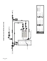
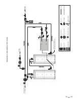
Ensure the cold water supply is not connected directly to or
Tee fi tted to the inlet water line on the HPWH. See the Service
and Installation Notes for Inlet & Outlet Water Temperature
on page 8. See Figure 7 and Figure 8 on page 16.
9. Connect building recirculation loop piping to the backup
water heater inlet on two tank preheat piping confi gurations.
10. Ensure the building recirculation loop pump is controlled by
a fi eld supplied line thermostat and that it stops the pump
when the recirculation line temp exceeds the manufacturer’s
specifi cations.
11. When the HPWH unit is installed above the storage tank install
a Tee fi tting at a high point in the outlet water line with a
purge valve to bleed air during start up.
12. The manufacturer recommends installing a strainer at the
inlet water line on the HPWH to help prevent scale build up
in the heat exchanger. Service costs to clear blockages from
the HPWH unit’s heat exchanger due to debris are not
covered under the limited warranty.
ELECTRICAL
13. BEFORE ENERGIZING THE UNIT ensure the power supply
voltage and phase matches the requirements on the HPWH
rating label. Damage resulting from applying the wrong
voltage or phase is not covered under the limited warranty.
14. Ensure the power supply breaker or the fuses disconnect
switch are within the requirements for the unit as shown
on the HPWH rating label.
15. Ensure the power supply wiring meets the MCA (Minimum
Circuit Ampacity) requirements shown in this manual and
on the HPWH data label.
16. Ensure the HPWH is properly grounded according to the
instructions in this manual and local code requirements.
17. Ensure the power supply connections to the HPWH are
connected properly and securely tightened.
18. Ensure all electrical connections in the HPWH control
panel are securely tightened.
19. When the factory supplied Temperature sensor is used:
•
Insure the sensor is installed properly.
•
Ensure the Temperature Sensor has been installed
in a designated temperature control opening in the
mid/lower portion of the storage tank.
•
Ensure the supplied Temperature Sensor is coated
with a suitable heat transfer compound (paste).
PRE-STARTUP CHECKLIST
1. Before applying power, check all electrical connections.
Tighten if necessary.
2. Verify electrical installation. Power requirements and
branch circuit disconnecting means match equipment
nameplate specifi cations.
3. Make sure the hydronic system is fl ushed and purged of
air. Remove and clean any strainers or fi lters if necessary.
4. Make sure the sensor for the temperature control is
mounted to either the water tank or strapped to a water
line for proper temperature control.
5. Remove the shipping blocks from under the compressor.
Loosen the nuts on the spring mounting studs and pry up
one side of the compressor at a time and remove. Leave
the nuts loose on the spring mounting studs.
6. Power up, (if fi eld supplied), external circulator pump and
verify water fl ow through the heat pump’s heat exchanger.
7. Turn on power to the heat pump. Confi rm power with an
electrical meter. Check for proper control power, should
be between 120 to 125 volts.
Note: The power should be on for 6 hours so the compressor
crankcase heater has time to warm up the base of the
compressor.
8. Start the heat pump by pressing the Start key on the
Touchscreen. Monitor the refrigerant pressure, hot
water in and out temperatures, and cold water in and
out temperatures.
It may be helpful to record the operating data initially every 10
to 15 minutes just to see how the heat pump is performing.
3 PHASE
STARTUP PROCEDURES
•
Make sure the disconnect is off and confi rm there is no
power on the distribution block on the electrical panel.
•
Pull Compressor fuses..
•
Turn power on. Check and make sure the power at the
distribution block is the same as the power requirements
on the data sticker that is on the electrical panel.
•
Make sure the compressor is going in the correct direction.
•
If it is going the wrong direction, then you need to switch
the phases. You will need to switch two of the legs that
you supplied to the distribution block. Make sure to turn
the power off before switching the phase. Confi rm there
is no power with an electrical meter then make the switch.
Confi rm the rotation is correct.
•
The factory temp setting is 125°F. If you would like to
change the temperature, then now is the time. (It can be
done later as well, NEVER SET HIGHER THAN 160°F).
•
Turn power off .
Summary of Contents for HS 50 Series 100
Page 2: ......
Page 10: ...6 WATER TO WATER CYCLE ...
Page 32: ...28 TABLE 10 FIGURE 12 ...
Page 41: ...37 Technical Support 1 833 447 3201 ...
Page 42: ...38 Service Log Issue Description Date Servicer ...
Page 43: ...39 Service Log Issue Description Date Servicer ...
Page 44: ......


