18
•
Double check to make sure all the air is out of the water
line so the heat pump doesn’t get air bound.
•
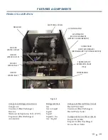
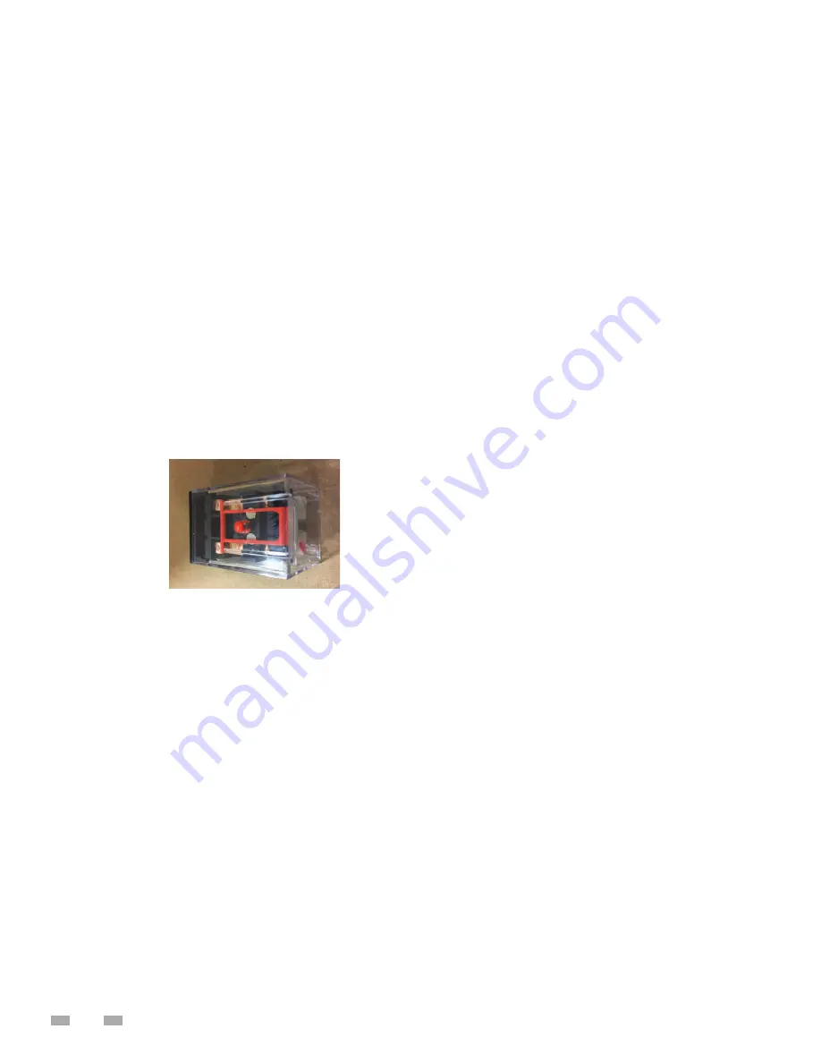
Pump Test – With the compressor fuses pulled Turn the
power back on. See figure #1. Press the orange by-pass
button on the pump relay to operate the water pump.
You should be able to hear the water flowing through
the system. and see a fl ow rate on the HMI/ Love control
(PLC or Basic Controls) If not, there is a good chance the
system is air bound and the air needs to be removed
before starting the compressor. Turn power back off after
test.
•
Turn power back on and the heat pump will start within 5
minutes if there is a call for heating.
•
Once the compressor starts, make sure to record the
amperage and that is doesn’t exceed the amperage on
the data sticker.
•
Measure the temperature on the water in and water out
lines. After the unit has been running for 15 minutes,
there should be a temp rise of 5°F or more.
•
Confirm the Flow rate on the water side is correct
(see manual for fl ow rates)
FIGURE #1
SINGLE PHASE
STARTUP PROCEDURES
•
Make sure the disconnect is off and confi rm there is no
power on the distribution block on the electrical panel.
•
***Warning*** Single phase systems have capacitors. You
should wait 5 minutes after turning the power off to service
it. Capacitors can hold a charge even when the power is
off .
•
Pull Compressor fuses.
•
Turn power on.
•
Check and make sure the power at the distribution block
is the same as the power requirements on the data sticker
that is on the electrical panel.
•
The factory temp setting is 120°F. If you would like to
change the temp, then now is the time. (It can be done
later as well,
NEVER SET HIGHER THAN 160°F
).
•
Turn power off .
•
Double check to make sure all the air is out of the water
line so the heat pump doesn’t get air bound.
•
Pump Test – With the compressor fuses pulled and the
blower/fan motor starter in the off (tripped) position. Turn
the power back on. See fi gure #1. Press the orange by-pass
button on the pump relay to operate the water pump.
•
You should be able to hear the water fl owing through the
system. and see a fl ow rate on the HMI/ Love Control (PLC
or basic controls) If not, there is a good chance the system
is air bound and the air needs to be removed before starting
the compressor.
•
Turn power back on and the heat pump will start within 5
minutes if there is a call for heating.
•
Once the compressor starts make sure to record the
amperage and that is doesn’t exceed the amperage on
the data sticker.
•
Measure the temp on the water in and water out lines. After
the unit has been running for 15 minutes, there should be
a temp rise of 5°F or more.
• Confi rm the Flow rate on the water side is correct (see
manual for fl ow rates.
INITIAL START-UP
CAUTION OIL DILUTION! Bearing malfunction! It is important
to ensure that new compressors are not subjected to liquid
abuse. Turn the crankcase heater on 4 - 6 hours before starting
the compressor. CAUTION High discharge pressure operation!
Compressor damage! Do not use compressor to test opening
set point of high-pressure cutout. Bearings are susceptible
to damage before they have had several hours of normal
running. Liquid and high pressure loads could be detrimental
to new bearings. It is therefore important to ensure that
new compressors are not subjected to liquid abuse and
high-pressure run tests. It is not good practice to use the
compressor to test the high-pressure switch function on the
production line. Switch function can be tested with nitrogen
prior to installation and wiring can be checked by disconnecting
the high-pressure switch during the run test.
MASTER CONTROL PANEL PRE-STARTUP
1. Mount the master control panel close to the Heat Pump
Water Heaters, tank(s), and to a 120/1/60 power source.
2.
Remove the control fuse in and connect the Master Control
Panel to the 120/1/60 power source, the incoming power
terminations are labeled.
3.
Run an Ethernet cable between the Master Control Panel’s
switch and each Heat Pump Water Heater. You will need
to make these cables on site and feed them through the
marked connection points. Refer to the electrical diagram
for connection information.
4. IMPORTANT: The Master Control Panel in any multi-unit
confi guration will have the only temperature probe.
(units working individually will not use a Master Control
Panel and will each have their own tank temperature
probe) Install the tank temperature probe in a designated
temperature control opening in the mid/lower portion of
Summary of Contents for HS 50 Series 100
Page 2: ......
Page 10: ...6 WATER TO WATER CYCLE ...
Page 32: ...28 TABLE 10 FIGURE 12 ...
Page 41: ...37 Technical Support 1 833 447 3201 ...
Page 42: ...38 Service Log Issue Description Date Servicer ...
Page 43: ...39 Service Log Issue Description Date Servicer ...
Page 44: ......

