26
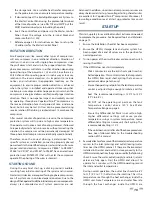
“CTD”
– Compressor Time Delay: indicates remaining time in
compressor delay countdown“PTD” – Pump Time Delay: indicates
remaining time in pump countdown, when the count down
starts the pump turns on
Remote Mode Indicator
– indicates if this unit is connected
to a master panel via Ethernet, if it isn’t then it will display a
start button
Alarm Indicator
– indicates if there is a system alarm, click on
the button to see which alarm is currently triggered
Defrost Indicator
– indicates if the unit is in a defrost cycle (in
a defrost cycle the compressor shuts off and lets the fans run
to warm up the evaporator)
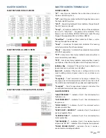
ALARM SCREEN
“HIGH PRESSURE” –
indicates if the unit has alarmed out on
high pressure
“LOW PRESSURE”
– indicates if the unit has alarmed out on
low pressure “SHORT CYCLE” – indicates if the unit has been
short cycling
“OUTLET FLOW”
– indicates if the unit has alarmed out on
condenser water fl ow
“Evap Flow”
– indicates if the evaporator has fl ow.
“M PROTECTION”
– indicates if the unit has alarmed out on
motor protection
“ESTOP”
– indicates if the unit has alarmed out because an
Estop has been pressed
“FAILOVER 1”
– indicates if the unit’s temperature probe has failed
“OIL PRESSURE”
– indicates if the unit has alarmed out on oil
pressure
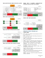
CONFIGURATION SCREEN
“TempDiff ”
– Temperature Diff erence: sets the temperature
difference below setpoint where the unit will turn on (only
available if the unit isn’t in remote mode)
“Capacity”
- Set-able value (gallons) of tanks storage capacity.
“CondFlow”
– Condenser Flow: indicates the fl ow-rate
through the condenser (based on frequency read by PLC
through integrated paddle wheel fl ow sensor)
“Low Limit”
– Sets the lowest fl ow rate limit that the unit will
shut off at (enabled for Single-Pass applications only), press the
save button to save the lower limit in a Single-Pass confi guration
“Comp HRS”
– Compressor Hours: indicates the run hours of
the compressor
“Purge” button
– this button will run the pump relay for 2
minutes to allow you to purge the system without turning on
the units
“Tank/Pipe”
- Unit call probe location, probe is recommended
inside of tank whenever possible.
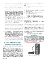
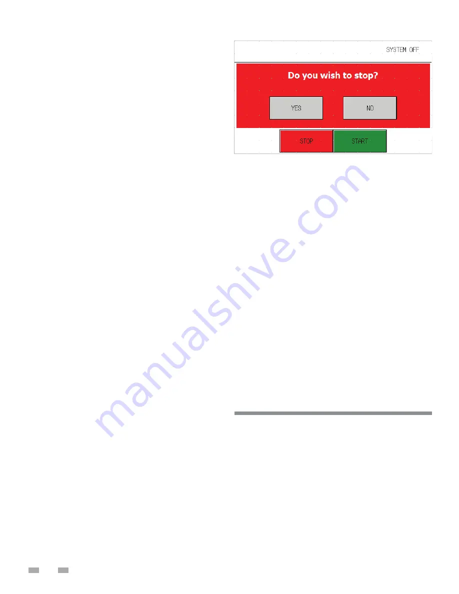
STOP SCREEN
The stop screen will pop up as a confi rmation whenever the
“STOP” button on any screen is pressed.
IP CONFIGURATION
New Lochinvar units can be configured for a variety of
different networks on the fly and the procedure is quick
and easy to accomplish.
1. Connect the Sim/Configuration Jumper to your
Lochinvar Systems WHP250 Unit you would like to
confi gure.
2.
Navigate to the “Diag” button in the bottom right corner of
your screen and select “IP Confi guration”
Unit IP Address – This IP address is the designation for the unit
itself, Lochinvar recommends running the system on factory
settings (ex. 192.168.1.(“Unit Number” AKA 1))
Unit IP Subnet – This number is used to determine the size of
the network the unit is connecting to. (ex. 255.255.255.0)
Master IP Address – This is the address of the Lochinvar
Systems Master Panel (ex. 192.168.1.50)
Unit Number – Only used for custom network confi gurations,
this confi gures your Lochinvar unit to connect to a Master Panel
under a desired number.
ROUTINE MAINTENANCE
Warning: When possible, disconnect all power to the unit and
follow the prescribed lock - out/tag - out procedure to
prevent accidental electrocution. Should the unit have to be
serviced with live electricity, only trained and qualified
technicians should carry out the service. Failure to follow all
of the safety warnings may result in serious injury or death.
The temperature-pressure relief valve must be manually
operated at least once a year. Caution should be taken to ensure
that (1) no one is in front of or around the outlet
of the temperature pressure relief valve discharge line,
and (2) the water manually discharged will not cause any
bodily injury or property damage because the water may be
extremely hot. If after manually operating the valve, it fails to
MAINTENANCE AND SERVICE
Summary of Contents for HS 50 Series 100
Page 2: ......
Page 10: ...6 WATER TO WATER CYCLE ...
Page 32: ...28 TABLE 10 FIGURE 12 ...
Page 41: ...37 Technical Support 1 833 447 3201 ...
Page 42: ...38 Service Log Issue Description Date Servicer ...
Page 43: ...39 Service Log Issue Description Date Servicer ...
Page 44: ......


