27
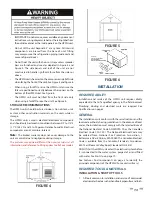
completely reset and continues to release water, immediately close
the cold water inlet to the heat pump, follow the draining
instructions in the storage tank manual, and replace the
temperature-pressure relief valve with a properly rated/sized
new one.
If you do not understand these instructions or have any questions
regarding the temperature-pressure relief valve call the toll
free number listed on the back cover of this manual for technical
assistance.
CLEANING INTERNAL INSULATION
Inspect the internal insulation on a yearly basis for any microbial
growth. The insulation never has to be cleaned unless microbial
growth is detected. If microbial growth is detected, follow the
removal steps below:
1. Disconnect all power to the unit and follow the prescribed
lock-out/tag-out procedure.
2. Wear the prescribed personal protective equipment
prescribed from the cleaning product instructions.
3. Remove as much dirt and organic material from the insu-
lation using a vacuum device with a HEPA fi lter (99.97%
effi
cient at 0.3 micron particles). Be careful not to tear the
insulation during the cleaning procedure.
4. Apply the microbial cleaning agent as prescribed by the
application and usage instructions.
5. Allow the unit to dry thoroughly.
6. If necessary, apply an anti-microbial agent on the insulation
per the instructions provided on the product label.
Discard collected microbial contaminants as required by local
or state codes.
CHECKING REFRIGERANT CHARGE
Servicing of the refrigeration circuit must only be performed
by agencies or individuals possessing Type II or Universal
certification as defi ned in Section 608 of the Clean Air Act.
See Qualifi cations on page 3.
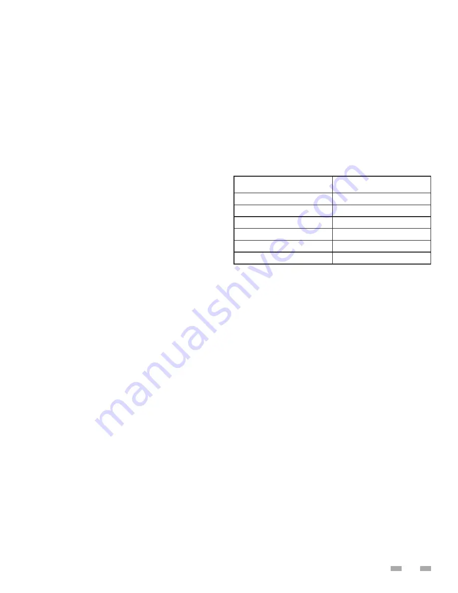
This HPWH unit is factory charged with 134a refrigerant. See
the rating label on the HPWH unit and Table 9 for refrigerant
charge by weight. It should not be necessary to add or
remove refrigerant during installation or start up. Refrigerant
lost during frequent refrigerant pressure testing can cause
low refrigerant conditions. Air and water fl ow should always
be checked fi rst to eliminate other potential problems before
checking the refrigerant charge.
CHECK WATER TEMPERATURE RISE
Always check water temperature rise through the HPWH
unit’s internal heat exchanger before checking the refrigerant
charge. See Start Up on page 19 for information on how to
measure the water temperature rise.
If the measured water temperature rise during start up was
within 8°F to 12°F (4°C to 7°C) checking the charge is not
necessary unless other conditions warrant testing.
If the measured temperature rise through the HPWH unit is
less than 8°F (4°C) checking the charge is not necessary
unless other conditions warrant testing. Short water piping
runs between the HPWH and the storage tank will produce
lower temperature rises and are not problematic.
If the measured temperature rise through the HPWH unit is
more than 12°F (7°C) check for restrictions in the inlet and outlet
water piping connected between the HPWH unit and the storage
tank.
TABLE 9
SUPERHEAT CALCULATION
1. Measure and record the suction pressure at the
suction line pressure access port inside the unit.
2. Convert the recorded suction pressure to saturated
temperature.
3. Measure the suction line temperature near the suction
line pressure access port inside the unit.
4. Compare the suction line temperature to the saturated
temperature in Table 10 on the next page.
5. The di
ff
erence between saturated temperature and
suction line temperature is the superheat. Superheat
normal range should be 8°F to 12°F (4.4°C to 6.7°C)
BRAZE PLATE CLEANING INSTRUCTIONS
In some applications the heat exchanger may be subjected
to severe fl uid conditions, including high temperature hard
water conditions, causing accelerated scaling and corrosion
rates, and will diminish performance.
It is important to establish regular cleaning schedules, A 5%
solution of Phosphoric Acid or Oxalic Acid may be considered.
Other types of solutions can be obtained from your local
wholesaler. Make sure cleaning solution is applicable for stainless
steel and copper and all directions are followed.
Do not heat solution. Be sure to fl ush heat exchanger with
fresh water after cleaning. See Figure 12 on the next page.
Model
Factory Charge R134A
WHP025
7 #
WHP060
14 #
WHP090
21 #
WHP125
25 #
WHP185
30 #
WHP250
50 #
Summary of Contents for HS 50 Series 100
Page 2: ......
Page 10: ...6 WATER TO WATER CYCLE ...
Page 32: ...28 TABLE 10 FIGURE 12 ...
Page 41: ...37 Technical Support 1 833 447 3201 ...
Page 42: ...38 Service Log Issue Description Date Servicer ...
Page 43: ...39 Service Log Issue Description Date Servicer ...
Page 44: ......

