11
6
Parameters
(continued)
Changeable parameters
The following is a brief discussion of the changeable
parameters, their default settings, the range of adjustment,
and their location. The title for the parameters may differ
slightly from the PC to the boiler display. To prevent
confusion, the boiler display version will be listed in
parenthesis.
Set 1: System setup
Set 1 is accessed by clicking on
Parameters
at the top of the
Main Screen window (FIG. 6-1), then on
Set 1: Control Setup
on the pull-down menu.
Ramp delay settings
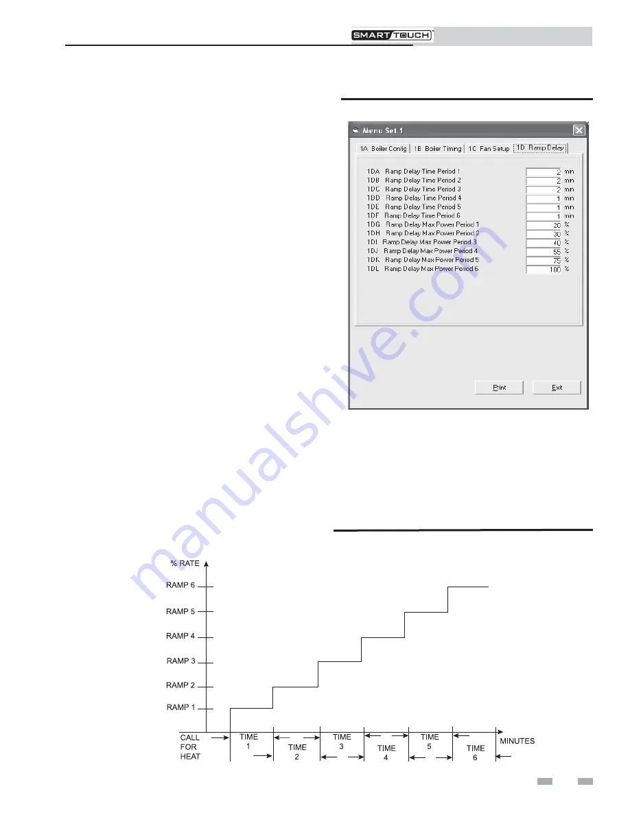
When active, the ramp delay limits the boiler firing rate when
a SH cycle has started
*
. There are 6 limiting steps used to
limit temperature overshoot and short cycles (see FIG. 6-2).
This feature can be turned on or off depending on the
installation. The default condition for this feature is disabled.
It should only be needed when the flow through the heat
exchanger is very low, or the flow in the primary loop can be
less than the flow in the secondary loop. The time for each of
the 6 ramp delays as well as the power level for each of the 6
ramp delays are adjustable. The time range for each ramp
delay is adjustable from 1 minute to 40 minutes with the total
of all 6 ramp delays not to exceed 109 minutes. The default
delay time for Periods 1, 2, and 3 is 2 minutes. The default
delay time for Periods 4, 5, and 6 is 1 minute. This process can
also work in reverse when the boiler shuts off. After shutting
off, the max firing rate will be limited to the ramp 6 limit for
the period 6 time delay, then to the ramp 5 limit for the period
5 time delay, and so forth. This step down feature overrides
the step up feature until the ramp up limit becomes higher
than the ramp down limit. To access the Ramp Delay settings,
click on the tab labeled 1D Ramp Delay (see FIG. 6-2).
Figure 6-2
Parameter Set 1D
The power range for each ramp delay is adjustable from 0 to
100. The defaults for each ramp delay is ramp delay 1= 20%,
ramp delay 2=30%, ramp delay 3=40%, ramp delay 4=55%,
ramp delay 5=75%, ramp delay 6=100% (FIG. 6-3). Note that
the limit in period 6 will limit the firing rate throughout the
entire call for heat. The locations for these parameters are
1DG through 1DL. See parameter 4FE (page 17 of this
manual) to enable or disable the ramp delay feature.
Figure 6-3
Ramp Delay Interval
PC Program Instructions
*
This is recommended for single-boiler installations only.


