background image

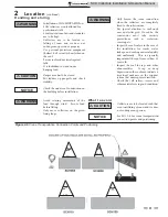
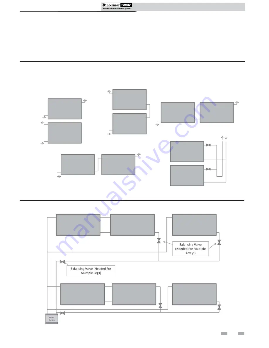
Figure 2-2 Multiple Array Piping


SCH Collectors Installation & Operation Manual

7

2  

Location

Array options

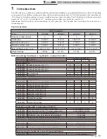
For series and parallel connection of multiple collectors, it is advisable to calculate the pressure drop over the entire system with 
the aid of the enclosed documents and to install an appropriate pump if necessary. The maximum collector area per collector 
array connected in series is 260 ft

2

. Be aware of pressure drop, reference the array options (FIG.’s 2-1 and 2-2).

Figure 2-1 Array Piping

SINGLE COLLECTOR

SERIES STACKED

PARALLEL SIDE BY SIDE

PARALLEL WITH BALANCING VALVES

(ON ROOF ONLY)

SERIES SIDE BY SIDE

Summary of Contents for TISUN SCH-I-O

Page 1: ...ust only be used by a qualified heating installer service technician Read all instructions before installing Perform steps in the order given Failure to comply could result in severe personal injury d...

Page 2: ...FINITIONS 2 1 INTRODUCTION 3 6 Technical Data 3 How It Works 4 Components 4 Descriptions 4 2 LOCATION Array Options 7 Installation Positions 8 Handling and Storing 9 What to Avoid 9 3 ROOF ATTACHMENT...

Page 3: ...m bar 13 ft 2 SCA20003 Horizontal aluminum bar 16 ft 2 SCA20004 Horizontal aluminum bar 20 ft 2 SSK20004 End bracing kit 2 2 2 2 SSK20005 Z hook kit 2 3 3 3 Inclined 20 40 60 installation SCA20001 Hor...

Page 4: ...outlet connection as shown on the collector label The sensor must be inserted up to the end of the sensor well 11 Plug This plug is used on the end collector of each array to complete the water flow...

Page 5: ...ts will have to be used Roof pitches in excess of 30 also represent increased loading additional mounting brackets must also be used for this variant CAUTION CAUTION SCH Collectors Installation Operat...

Page 6: ...cessed during the installation process 1 Introduction Check the materials for any damage sustainedintransportanddescribeany damage in writing on the packing slip where necessary This is important to p...

Page 7: ...rop over the entire system with the aid of the enclosed documents and to install an appropriate pump if necessary The maximum collector area per collector array connected in series is 260 ft2 Be aware...

Page 8: ...eestanding Installations min 15 max 70 Forbestperformance itisrecommended that the collectors face true south NOTICE It is not recommended for the collector field to deviate any further than 45 from t...

Page 9: ...y and check stability CAUTION Check the under roof construction on the building before installation NOTICE Only loosen the crane connection when the collectors are completely fixed to the substructure...

Page 10: ...ns SRM20007 PLATE FLANGE SHINGLE STD X X X 20 Galvanized steel attachment for parallel inclined and freestanding installations on asphalt or elastomer roofs SRM20008 PLATE FLANGE SHINGLE RAISED X X 22...

Page 11: ...4 lb sq ft area load up to 16 lb sq ft area load up to 32 lb sq ft SCH065 6 10 6 10 SCH090 8 12 8 12 SCH110 8 14 8 14 SCH130 10 18 10 18 Parallel installation SRM 20001 20003 20004 20007 20008 20009 2...

Page 12: ...end attachments will be spaced according to the inner measurement start in the middle and work outwards The remaining roof mounts should be equally spaced in between the two 2 end roof attachments Not...

Page 13: ...3 Pre Drill 9mm Holes Into Substructure PRE DRILL TWO 2 9MM HOLES PERPENDICULAR TO THE ROOF APPROX 4 IN DEEP INSTALL HANGER BOLT S 6 Slide the hanger bolt seals over the machine threads until the seal...

Page 14: ...into the opening of the double hanger bolt plate as shown in FIG 3 5 Note Do not tighten hex bolts until ready to install on the collector substructure 15 Thread the hex nut M8 and washer M8 onto the...

Page 15: ...oof type Inspect the structural integrity of the roof and the durability of the roof materials 2 Determine the number of collectors needed for the installation and the number of required roof attachme...

Page 16: ...X BOLT M8 1X WOOD SCREW 1X NAIL 3X WASHER M8 1X SQUARE DISK 1X METAL SHEET 1X 3 Roof Attachment Installation 11 Slide the square disk onto the hex bolt see FIG 3 8 12 Install the hex bolt with square...

Page 17: ...e kit secure the metal sheet to the roof substructure FIG 3 11 8 Secure the tiled roof hook to the roof substructure using the screws provided in the kit FIG 3 11 9 Replace the tile removed in Step 5...

Page 18: ...ber of collectors needed for the installation and the number of required roof attachments from Table 3B and 3C on page 11 3 Determine collector connection points spacing Measure the spacing of the raf...

Page 19: ...not reuse any stainless steel screws as there is a risk of breakage CAUTION Install cable securing kit 1 Install the anchor bracket on the A frame using the hex bolt square disk washer and hex nut 2 A...

Page 20: ...xtend turnbuckle to its fullest extent NOTICE 7 Before tightening the joint clamp set the angle of the cable to greater than or equal to 30 but less than or equal to 45 see FIG 3 20 8 Tighten the join...

Page 21: ...ning 6 Install the four 4 remaining smaller screws in the perimeter of the flange plate as shown in FIG 3 23 caulk around screws before tightening 7 Cover flange plate with roofing material sealing it...

Page 22: ...ntegrity of the roof and the durability of the roof materials 2 Determine the number of collectors needed for the installation and the number of required attachments from Table 3B or 3C on page 11 3 D...

Page 23: ...rofiled or corrugated sheet metal roofs The console is mounted above the mounting screws of the profiled or corrugated sheet metal The two sealing screws are first screwed onto the underlying mounting...

Page 24: ...f the metal roof attachment see FIG 3 31 7 Install hex bolts into pre drilled holes as shown in FIG 3 32 8 Install the four 4 self tapping screws provided in kit into each side of the metal roof attac...

Page 25: ...the system check the model names of the components of each system and check to be sure you have the correct number of parts see FIG 3 34 Install wave roof attachment 1 Determine roof type Inspect the...

Page 26: ...rofile with a 10 5 mm clearance hole is threaded over the bolt and fixed with a washer and nut There are two 2 models of concrete anchor bolts one with adjustment and one without The adjustable dimens...

Page 27: ...anchor bolt with adjustments 7 Drill a 10 5 mm hole in the horizontal bar see FIG 3 39 8 Place the horizontal bar onto the anchor bolt and use the remaining washer and nut to secure the horizontal ba...

Page 28: ...lation Operation Manual 4 Collector Installation Horizontal bar lengths Figure 4 1A Horizontal Bar Lengths 6 7 x x SCH065 9 10 SCH090 13 2 SCH110 16 4 SCH130 19 7 x x x x Figure 4 1B Spacing Informati...

Page 29: ...Lifting Rings 30 6 5 ft 30 6 5 ft 30 6 5 ft 30 8 5 ft 5 Position the collector onto the substructure and hanger brackets FIG 4 5 Figure 4 5 Position Collector On Substructure POSITION PANEL ONTO SUBST...

Page 30: ...re 4 9 For Stacked Series Installations Use Self Tapping Screws and Spacers USE SELF TAPPING SCREWS AND SPACERS TO SEPARATE THE TOP PANEL FROM THE BOTTOM PANEL 10 Install top collector on the horizont...

Page 31: ...EINSTALL COLLECTOR RAILING OPTIONAL MECHANICAL CONNECTION KIT 15 Install the side by side bracket using the square disks and hex bolts provided in the kit FIG 4 16 Figure 4 16 Install Side by Side Bra...

Page 32: ...each other 7 Install three 3 U channel supports FIG 4 23 Drill a 4 mm hole through the bracket and U channel use pop rivets to attach the U channels perpendicular to the A frame Figure 4 23 Install Ho...

Page 33: ...ing the square disk and bolt provided in the kit FIG 4 28 15 Ensure all bolts are tightened Figure 4 28 Install Top End Brace CONNECT COLLECTOR TO END BRACE 33 SCH Collectors Installation Operation Ma...

Page 34: ...nstall Side by Side Bracket INSTALL SIDE BY SIDE BRACKET 17 Remove the collector railing and install the Mechanical Connection Kit FIG s 4 30 and 4 31 Note Be sure to bend the tabs down on the Mechani...

Page 35: ...able 4A Inclined and Non South Facing Installations A B c d 20 6 ft 7 in 24 in 6 in 4 in 40 6 ft 7 in 47 in 7 in 4 in 60 6 ft 7 in 69 in 8 in 4 in 4 Collector Installation continued SCH A frame dimens...

Page 36: ...frame 40 inclined 2 3 3 4 SSK20003 A frame 60 inclined 2 3 3 4 Hydraulic connection kits 1 array is max 2 SCH s HYK20001 Hydr conn kit 2x 6 5 plug sensor well 1x per collector or array HYK20002 Hydr...

Page 37: ...ollectors connected in this way Be aware of pressure drop see the Recommended Flow Chart on page 38 Use a more powerful solar pump if necessary Hydraulic connection kits The hydraulic connection kits...

Page 38: ...nsulation supplied is pulled over the corrugated pipe and fixed in place with the adhesive tape included in the set The insulation is suitable for temperatures up to 347 F and resistant to UV radiatio...

Page 39: ...lation Operation Manual MODEL NO RECOMMENDED FLOW GPM PRESSURE DROP FT OF HD SCH065 0 656 1 06 SCH090 0 872 1 66 SCH110 1 090 2 51 SCH130 1 300 3 59 NOTICE The above chart references recommended flow...

Page 40: ...ety instructions can result in the destruction of and defects on the expansion tank endanger persons and impair the operation Final checks before starting the system Read the Lochinvar TiSun Different...

Page 41: ...urn ball valves Activate speed control on solar control unit The highest speed level should be set on the pump phase control Note The minimum speed set on the solar control unit must not fall below th...

Page 42: ...owner and correct before proceeding Fluid installation Follow these installation procedures 1 Clean new or lightly corroded existing systems with a 1 or 2 solution of trisodium phosphate in water pri...

Page 43: ...th its discharge in a safe area to avoid severe scald potential WARNING 5 Check Freeze Protection Fluid ensure that the heat transfer fluid has the proper concentration of glycol as recommended in thi...

Page 44: ...Revision Notes Revision A ECO C06510 initial release SCH I O Rev A 9 10...

Reviews: