KELLY STAND
LOCO - 124 USER MANUAL
Page
5
Select Healthcare (UK) Ltd
Unit 2 Albert Road
Rushden
Northants
NN10 0BU Tel:
01933 411729 Fax: 01933 410213
Designed and Developed by: Proto Magic Innovations Ltd Page 5
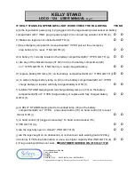
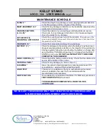
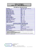
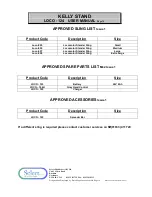
KELLY STAND INSTRUCTIONS 07
1.
Getting Started with your Locomotor KELLY STAND
1.1. Remove all items from the carton.
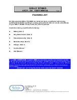
1.2. Identify the items and their quantities against the packing list.
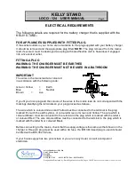
1.3. Plug the battery charger (7) into a 13 amp mains socket and switch on. A green light will
indicate mains input to the charger (8). Place battery (1) into the charger (7), the amber
light (9) will indicate that battery is charging. When the battery is fully charged the amber
light will go out.
2.
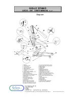
Assembly of your Locomotor KELLY STAND (See diagram)
2.1. Place the base chassis (4) on a level floor.
2.2. Locate the mast assembly (5) onto the chassis spigot (10), then lock with the mast lock
hand wheel (11).
2.3. Plug the lead for the powered leg opener (12) onto the leg actuator power socket (13) on
the under side of the battery compartment(28).
2.4.
Plug the lead for the lift actuator (18) onto the lift actuator power socket (6) on the back of
the battery compartment (28).
2.5 Place a charged battery (1) in the battery compartment (28).
Connect the hand control (3) into the socket on the battery compartment(15).
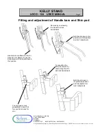
2.6 The height of the shin pad can be adjusted using the hand wheels as shown on page # 3. if
further adjustment is required then the shin pad can be removed from its attachment
bracket by removing the two fixing screws and re attaching it higher or lower by using the
alternative and offset fixing holes.
2.7 To dismantle for transportation, reverse the above procedure.


