background image

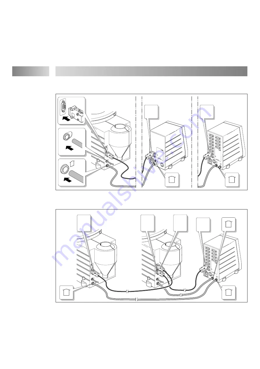
Anschließen eines Automatikbehälters an das Steuergerät 97102 oder 97103

Anschließen von zwei Automatikbehältern an das Steuergerät 97103

Installieren

4

14

XS2/IN: Controller
XS2/OUT:Tank B

max. operating pressure
8 bar

operating temperature.
0 to +50C

volume:
3,5 Liter

Loctite (Ireland) Ltd.

Made in Germany

XS2/IN

XS2/OUT

P in

A

B

85–264 VAC/50–440 Hz
                      2 AM   

XS1: Start
XS2: Reservoir
XS3: Turntable
XS4: DC Motor
XS5: Monitor A
XS6: Monitor B
XS7: RS232 Master
XS8: RS232 Slave
XS9: PLC Interface
XS10: I/O port
XS11: Servo A/B
XS12: Channel A/B

Loctite (Ireland) Ltd.

Made in Germany

cat.no.97103

XS1

XS2

XS3

XS4

XS5

XS12

XS11

XS10

XS9

XS6

XS7

XS8

90–260 VAC/47–63 Hz
                  2 AM   

XS1

XS1: Start
XS2: Reservoir

Loctite (Ireland) Ltd.

Made in Germany

cat.no.97102

XS2

97106
97108

97102

97103

A

XS2

XS2

XS2/IN

P in

XS2/IN: Controller
XS2/OUT:Tank B

max. operating pressure
8 bar

operating temperature.
0 to +50C

volume:
3,5 Liter

Loctite (Ireland) Ltd.

Made in Germany

XS2/IN

XS2/OUT

P in

A

B

85–264 VAC/50–440 Hz
                      2 AM   

XS1: Start
XS2: Reservoir
XS3: Turntable
XS4: DC Motor
XS5: Monitor A
XS6: Monitor B
XS7: RS232 Master
XS8: RS232 Slave
XS9: PLC Interface
XS10: I/O port
XS11: Servo A/B
XS12: Channel A/B

Loctite (Ireland) Ltd.

Made in Germany

cat.no.97103

XS1

XS2

XS3

XS4

XS5

XS12

XS11

XS10

XS9

XS6

XS7

XS8

97103

A

XS2/IN

XS2/IN

XS2/OUT

XS2

B

97106
97108

97106
97108

Summary of Contents for 97105

Page 1: ...R R 97105 97106 97107 97108 ...

Page 2: ......

Page 3: ...3 XS2 IN Controller XS2 OUT Tank B max operating pressure 8 bar operating temperature 0 to 50C volume 3 5 Liter Loctite Ireland Ltd Made in Ge rmany XS2 IN XS2 OUT P in R 1 2 3 5 9 8 7 6 11 10 4 12 13 ...

Page 4: ...2 97123 97118 97115 97119 97109 97106 97125 97108 97127 97105 97107 97110 97007 97009 97103 97204 1x 1x 1x 1x 1x 97112 97116 97121 97113 97114 97134 97135 97136 97112 97116 97121 97113 97114 COA X 0 1 COA X 0 1 2 1 2 1 2 1 2 1 97134 97135 97136 ...

Page 5: ...5 Deutsch 6 22 English 23 39 ...

Page 6: ...älter 12 4 4 Anschließen der Geräte 13 5 Dosieren 15 5 1 Erste Inbetriebnahme 15 5 1 1 Einsetzen der Produktflasche 15 5 2 Nachfüllen des Produktbehälters Auswechseln der Produktflasche 16 5 3 Außerbetriebnahme 17 5 4 Erneute Inbetriebnahme 17 6 Pflege Reinigung und Wartung 17 7 Beseitigen von Störungen 18 8 Technische Unterlagen 18 8 1 Zubehör und Ersatzteile 20 8 2 Belegung des Druckluftanschlus...

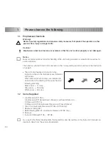
Page 7: ...Handlungsschritte in Abbildungen sind durch Pfeile dargestellt Werden mehrere Handlungsschritte in einer Abbildung dargestellt bedeutet ein Schwarzer Pfeil 1 Handlungsschritt Grauer Pfeil 2 Handlungsschritt Weißer Pfeil 3 Handlungsschritt 1 2 Lieferumfang 1 0 5 l Produkttank 97105 oder 0 5 l Produkttank 97106 Automatikbehälter mit Füllstandsanzeige oder 2 l Produkttank 97107 oder 2 l Produkttank 9...

Page 8: ...ng muß der Produkttank entlüftet drucklos sein Siehe Abschnitt 5 1 Das Gerät darf nur vom autorisierten Loctite Service repariert werden Niemals das Produkt direkt in den Tank füllen Die Sicherheitseinrichtungen werden verklebt und dadurch unwirksam Das Produkt nur im LOCTITE Originalgebinde einsetzen 1 4 Einsatzbereich Mit dem 0 5 Liter Produkttank 97105 oder 97106 kann LOCTITE Produkt direkt aus...

Page 9: ...sto weniger Produkt ist noch vorhanden 1 rote LED Leer Empty Der Automatikbehälter wird durch das Steuergerät 97102 oder 97103 automatisch entlüftet und kann erst nach dem Auswechseln der leeren Produktflasche gegen eine gefüllte wieder automatisch belüftet werden siehe Abschnitt 5 3 5 Entlüftungsventil Schalterstellung Der Produkttank ist entlüftet Schalterstellung Der Produkttank kann belüftet w...

Page 10: ...et ist wird durch pneumatischen Druck auf die Flüssigkeitsoberfläche in der LOCTITE Originalflasche das Produkt durch die Produktleitung gefördert Nur Automatikbehälter Bei Anschluß an ein Steuergerät 97102 oder 97103 wird der Automatikbehälter beim Einschalten des Steuergerätes automatisch belüftet und beim Ausschalten des Steuergerätes automatisch entlüftet Das Entlüftungsventil 5 muß in Schalte...

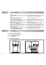
Page 11: ...tallieren Zubehör Bestellnummer 97120 Überdrucksicherung Berstscheibe min 9 bar 130 5 psi max 12 5 bar 174 psi Anzugsmoment der Berstscheibe max 20 Nm Schlauchgröße Druckluftanschluß P in Außen Ø 6 mm Schlauchgröße Druckluftanschluß koaxial Außen Ø 9 5 mm TW09 B 20 Fa SMC Abmessungen 0 5 l 2 l Produkttank B x H x T 170 x 255 x 315 mm 205 x 335 x 360 mm Betriebstemperatur 10 C bis 40 C 50 F bis 104...

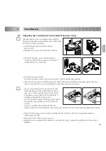
Page 12: ...8 passen den Füllstandsensor so heraus oder hineindrehen daß er die Produktflasche einklemmt Gegebenenfalls die Produktflasche mit geeigneten Hilfsmitteln gegen den Füllstandsensor pressen Im 0 5 l Produkttank den Sensorstecker bei geöffnetem Gehäuse gedreht montieren wie im linken Bild gezeigt ist An den Steuergeräten 97103 und 97123 muß der Produkttank im Peripherie Menü eingeschaltet sein siehe...

Page 13: ...die untere der beiden grünen LED s leuchtet Diese Einstellung wenn sie korrekt ist mit einer vollen Flasche und erneut mit der leeren Flasche prüfen Leere Produktflasche herausnehmen Gehäuse zuklappen Befestigungsschrauben wieder einsetzen und festziehen 4 4 Anschließen der Geräte Anschließen des Produkttanks 97105 bzw 97107 Installieren 4 13 Loctite Ire lan d Ltd Mad e in Germ any cat no 97 101 9...

Page 14: ...ny cat no 9 710 3 XS1 XS2 XS3 XS4 XS5 XS12 XS11 XS10 XS9 XS6 XS7 XS8 90 260 VAC 47 63 Hz 2 AM XS1 XS 1 Sta rt XS 2 Reservo ir Loctite Ire lan d Ltd Mad e in Germ any cat no 97 102 XS2 97106 97108 97102 97103 A XS2 XS2 XS2 IN P in XS 2 IN Co ntroller XS 2 OU T T ank B ma x opera ting pre ssu re 8 bar opera ting tem perature 0 to 50 C vol um e 3 5 Lite r Loctite Irela nd Ltd Ma de in Ger ma ny XS2 I...

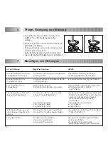
Page 15: ...ung 2 lösen und Deckel 1 abnehmen Prüfen daß das Dosierventil gemäß dessen Bedienungsanleitung korrekt angeschlossen ist Niemals das Produkt direkt in den Tank füllen Die Sicherheitseinrichtungen werden verklebt und dadurch unwirksam Eine volle Produktflasche in den Tank einsetzen Nur Automatikbehälter Prüfen daß die in den Flaschenhalter eingesetzte Produktflasche gegen den Füllstandssensor gepre...

Page 16: ...kttank entlüftet drucklos sein siehe Abschnitt 5 1 Deckelverschraubung 2 lösen Deckel 1 abnehmen Produktreste am Schlauch Deckel 1 auf den Auffangtrichter legen Die leere Produktflasche oder Kartusche im Produktbehälter gegen eine volle auswechseln Nur Automatikbehälter Prüfen daß die in den Flaschenhalter einge setzte Produktflasche gegen den Füllstands sensor gepreßt wird siehe Abschnitt 4 3 Den...

Page 17: ...ein siehe Abschnitt 5 1 Deckelverschraubung 2 lösen Deckel 1 abnehmen Produktreste am Schlauch Produktschlauch äußerlich von Produktresten reinigen 5 3 Außerbetriebnahme Die Druckluftversorgung unterbrechen Außerbetriebnahme für längere Stillstandszeiten Bei Arbeitspausen von länger als 14 Tagen das System außer Betrieb nehmen um Aushärtungen von Produkt zu vermeiden Die Druckluftversorgung unterb...

Page 18: ... 3 nicht festgezogen Berstscheibe zerstört Entlüftungsventil 5 offen oder defekt Stecker bzw Buchse des Anschluß kabels Produktbehälter lose Anschlußkabel defekt LED Anzeige 4 defekt Tankelektronik defekt Schlauch nicht korrekt montiert bzw Schlauch nicht sauber abgeschnitten Dosierdruck unzureichend Vordruck unzureichend Störung am Dosierventil Deckelverschraubung nachziehen O Ring nachfetten ode...

Page 19: ...stscheibe Bei Überschreitung der maximal zulässigen Druckluftversorgung wird der Produkttank durch die Berstscheibe entlüftet Die zerstörte Berstscheibe muß ausgewechselt werden Deckelverschraubung 2 lösen und Deckel 1 abnehmen Befestigungsschrauben entfernen und Gehäuse aufklappen Einschraubmutter für Berstscheibe entfernen Die zerstörte Berstscheibe gegen eine neue ersetzen Einschraubmutter für ...

Page 20: ...r 97250 2 2 l Tank Ersatzteilset 1 O Ring Silikonfett 3 Dreikantgriffe 3 Auffangbehälter 97253 3 Berstscheibe 97251 4 Anschlußkabel Produktbehälter 2 m 97213 5 Flaschenhalter für 2 l Tank mit Füllstandsanzeige 97202 6 Wartungseinheit 97120 8 1 Zubehör und Ersatzteile 8 2 Belegung des Druckluftanschlusses Geregelte Druckluft Ungeregelte Druckluft I 0 ...

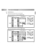
Page 21: ...iktank 1 2 1 2 Tank Ventil Tank nachfüllen Tank leer max 1 8 W Tank erkennung 24 VDC 1 2 3 4 5 6 7 8 9 0 VDC Signal Tank Ventil Tank nachfüllen Tank leer 1 0 1 0 1 0 1 2 3 4 5 6 7 8 9 GND 1 2 1 2 24 VDC 1 2 3 4 5 6 7 8 9 0 VDC 1 2 1 2 1 0 1 0 1 0 Tank Ventil B Signal Steuergerät XS2 2 Automatiktanks Tank Ventil A Tank A nachfüllen Tank A leer max 1 8 W Tank erkennung Tank Ventil Tank nachfüllen Ta...

Page 22: ...he wegen Nichterfüllung gemäß 463 480 Abs 2 BGB geltend macht Wird innerhalb der Gewährleistungsfrist ein Mangel festgestellt so ist das entsprechende Teil an Loctite zurückzusenden Ein Begleitschreiben mit Angabe der Rechnungsnummer unter der das Produkt bezogen wurde sowie der Ursache für die Rücksendung ist beizufügen Die Rücklieferung von Komponenten zur Reparatur muß ohne fremde Teile erfolge...

Page 23: ...el Sensor Automatic Reservoir Only 29 4 4 Connection of the Equipment 30 5 Dispensing 32 5 1 First Operation 32 5 1 1 Inserting the Product Bottle 32 5 2 Refilling the Product Reservoir Replacing the Product Bottle 33 5 3 Shutdown 34 5 4 Returning to Operation 34 6 Care Cleaning and Maintenance 34 7 Troubleshooting 35 8 Documentation 37 8 1 Accessories and Spare Parts 37 8 2 Pneumatic Connection C...

Page 24: ...ion step Instruction steps in the illustrations are indicated with arrows When several instruction steps are indicated in an illustration the shading of the arrow has the following meaning Black arrow 1st step Grey arrow 2nd step White arrow 3rd step 1 2 Items Supplied 1 0 5 l Reservoir 97105 or 0 5 l Reservoir 97106 Automatic Reservoir with Level Sensor or 2 l Reservoir 97107 or 2 l Reservoir 971...

Page 25: ...w fasteners the reservoir must be depressurized pressure free see Section 5 1 The unit must be repaired only by an authorized Loctite Service agency Never fill the product directly into the reservoir The safety devices would become clogged and therefore ineffective Insert only products in original LOCTITE packaging 1 4 Usage With the 0 5 liter Reservoir 97105 or 97106 LOCTITE Products can be appli...

Page 26: ...it LED is the less product is available 1 red LED Empty The automatic reservoir is automatically depressurized by the controller 97102 or 97103 and can be automatically repressurized only after the replacement of the empty product bottle with a full one see Section 5 3 5 Depressurizing valve Valve position The reservoir is depressurized Valve position The reservoir can be pressurized 6 Socket XS2 ...

Page 27: ...eumatic pressure on the surface of the fluid in the original LOCTITE bottle transports the product through the product line Automatic reservoir only When connected to a controller 97102 or 97103 the automatic reservoir is automatically pressurized when the controller is switched on and automatically depressurized when the controller is switched off The depressurizing valve 5 must be in the valve p...

Page 28: ...gulator Accessory Order No 97120 Over pressure safety rupture disc min 9 bar 130 5 psi max 12 5 bar 174 psi Tightening torque of the rupture disc max 20 Nm Pneumatic hose size External dia 6 mm Pneumatic hose size coaxial External dia 9 5 mm TW09 B 20 Co SMC Dimensions 0 5 l 2 l reservoir W x H x D 170 x 255 x 315 mm 205 x 335 x 360 mm Operating temperature 10 C to 40 C 50 F to 104 F Storage tempe...

Page 29: ...ottles which do not fit into the bottle nesting block 8 rotate the level sensor out or in so that it clamps the product bottle If necessary press the product bottle with a suitable aid against the level sensor For 0 5 l reservoir adjust the plug of the sensor by opening and rotating as shown in the left picture On the controllers 97103 and 97123 the product reservoir in the periphery menu must be ...

Page 30: ...orrect if the lower of the two green LED s are burning when a full bottle is inserted Check this adjustment with a full bottle and the empty bottle again if it is correct Remove the empty product bottle Close the housing Insert and tighten the screws 4 4 Anschließen der Geräte Anschließen des Produkttanks 97105 bzw 97107 Loctite Ire lan d Ltd Mad e in Germ any cat no 97 101 90 260 VAC 47 63 Hz 2 A...

Page 31: ... cat no 9 710 3 XS1 XS2 XS3 XS4 XS5 XS12 XS11 XS10 XS9 XS6 XS7 XS8 90 260 VAC 47 63 Hz 2 AM XS1 XS 1 Sta rt XS 2 Reservo ir Loctite Ire lan d Ltd Mad e in Germ any cat no 97 102 XS2 97106 97108 97102 97103 A XS2 XS2 XS2 IN P in XS 2 IN Co ntroller XS 2 OU T T ank B ma x opera ting pre ssu re 8 bar opera ting tem perature 0 to 50 C vol um e 3 5 Lite r Loctite Irela nd Ltd Ma de in Ger ma ny XS2 IN ...

Page 32: ... fasteners 2 and remove the cover 1 Check that the dispensing valve is connected correctly according to the instruction manual Never fill the product directly into the reservoir The safety devices would become clogged and therefore ineffective Insert a full product bottle in the reservoir Automatic reservoir only Check that the product bottle inserted in the bottle nesting block is pressed against...

Page 33: ...re free see Section 5 1 Loosen the cover screw fasteners 2 and remove the cover 1 Product residue on the hose Place the cover 1 on the drip funnel Replace the empty product bottle or cartridge in the product reservoir with a full one Automatic reservoir only Check that the product bottle inserted in the bottle nesting block is pressed against the level sensor see Section 4 3 Insert the product hos...

Page 34: ...ection 5 1 Loosen the cover screw fasteners 2 and remove the cover 1 Product residue on the hose Clean product residue from the outside of the product hose 5 3 Shutdown Disconnect the pneumatic supply from the unit Shutdown for Longer Periods of Non use For pauses in the work of longer than 14 days place the system out of operation to prevent curing of the product Disconnect the pneumatic supply f...

Page 35: ...oduct connection 3 not tightened Punctured rupture disc Depressurizing valve 5 open or defect Loose plug or socket of the tank cord on the product reservoir Tank cord defect LED indicator 4 defect Reservoir electronics defect Dispensing pressure inadequate Air supply pressure inadequate Malfunction of the dispensing valve Co axial air hose not correct connected or not cutted in a straight and clea...

Page 36: ...B A Troubleshooting 7 Replacing the Rupture Disc When the maximum allowable air supply pressure is exceeded the reservoir is depressurized by the bursting of the rupture disc he punctured rupture disc must be replaces Loosen the cover screw fasteners 2 and remove the cover 1 Remove the screws and open the housing Remove the rupture disc screw Replace the punctured rupture disc with a new one Repla...

Page 37: ...s 97250 2 2 l Reservoir Spare Part Kit 1 O ring silicone grease 3 handles 3 dripcups 97253 3 Rupture Disc 97251 4 Tank Cord 2 m 97213 5 Bottle Nesting Block for 2 l Reservoir with Level Sensor 97202 6 Filter Regulator 97120 8 1 Accessories and Spare Parts 8 2 Pneumatic Connection Convention I 0 Regulated Pressure Unregulated Pressure ...

Page 38: ...2 3 4 5 6 7 8 9 0 VDC 1 0 1 0 1 0 Controller XS2 Automatic Reservoir Tank REFILL Tank EMPTY max 1 8 W Identification Signal Tank Valve Tank Valve Signal Tank REFILL Tank EMPTY 1 2 3 4 5 6 7 8 9 GND 1 2 1 2 24 VDC 1 2 3 4 5 6 7 8 9 0 VDC 1 2 1 2 1 0 1 0 1 0 Controller XS2 2 Automatic Reservoirs Tank A REFILL Tank A EMPTY max 1 8 W Identification Signal Tank B REFILL Tank B EMPTY Tank Valve Tank Val...

Page 39: ...alled connected operated used or maintained or in the event of unauthorized modification or the Products including where products parts or attachments for use in connection with the Products are available from Loctite the use of products parts or attachments which are not manufactured by Loctite No Products shall be returned to Loctite for any reason without Loctite s prior written approval Produc...

Page 40: ...Loctite Ireland Ltd Tallaght Business Park Whitestown Tallaght Dublin 24 Ireland 1994 Loctite Corporation 8950077 05 99 ...

Reviews: