background image


Operating Manual
Bedienungsanleitung

Air Filter System LAS 250 
Luftfilter-System LAS 250 

97603 

Summary of Contents for 97603

Page 1: ...Operating Manual Bedienungsanleitung Air Filter System LAS 250 Luftfilter System LAS 250 97603 ...

Page 2: ...English 3 11 Deutsch 12 20 ...

Page 3: ... 3 Technical Data 7 4 Installation 8 4 1 Environmental and Operating Conditions 8 4 2 Connecting the Unit 8 4 3 Connecting the Suction Hose 8 4 4 Connecting the Suction Arm 8 5 Operation 9 6 Cleaning and Maintenance 10 6 1 General Instructions 10 6 2 Calculation of the Life Time of the Filter 10 6 3 Disposal 10 6 4 Changing the Filter 11 7 Troubleshooting 11 8 Accessories and Spare Parts 11 Declar...

Page 4: ...g operation or adjustment as well as for service activities The numbers printed in bold in the text refer to the corresponding position numbers in the illustration on page 6 The point emphasizes an instruction step Instruction steps are indicated in an illustration with black arrows 1 2 Items Supplied 1 Air Filter System LAS 250 type no 97603 order no 527595 1 Power Cord 1 Operating Manual As a re...

Page 5: ...r cord or the housing can result in contact with live electrical parts Check the power cord and the unit before each use If the power cord or the unit is damaged do not operate Replace a damaged power cord with a new one Do not remove by pass or disable any safety device It can result in damage to the unit and is therefore prohibited Never use the Air Filter System without the filter Unplug the Ai...

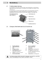
Page 6: ...tional View of the Filter 3 2 2 Displays Operating Elements and Connections 1 Suction Flanges 8 Stepless Adjustable Airflow 2 Removable Housing 9 Power Switch 3 Filter 10 Suction Hose not shown 4 Snap Locks 11 The Suction Arm not shown 5 Silencer cartridge with air outlet on the backside 10 and 11 are accessories They must be ordered separately 6 7 Housing mobile with integrated fan Operating Hour...

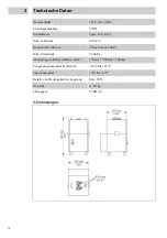
Page 7: ... 450 m h Constant Air Flow 250 m h at 2 200 Pa Max Vacuum 2 600 Pa Dimensions width x height x depth 370 mm 780 mm 500 mm 14 6 30 8 19 7 Ambient Operating Temperature 10 C to 45 C 50 F to 113 F Storage Temperature 5 C to 55 C 41 F to 131 F Relative Humidity for Storage Max 50 Weight 40 kg Noise Level 52 dB A Dimensions ...

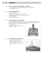
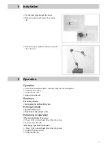
Page 8: ...t power cord to the unit 4 3 Connecting the Suction Hose The Air Filter System can be equipped via two Y splitters with four suction hoses for supplying up to four workplaces These Y splitters have to be mounted before the suction hoses are mounted The Y splitters have to be ordered separately Remove blind cap Push the suction hose 10 into the suction flange 1 or Y splitter 4 4 Connecting the Suct...

Page 9: ...ces Connect power plug Switch on the unit Adjust the airflow 8 Shutdown For short periods Decrease the airflow 8 to zero For longer periods Switch off the unit Disconnect the power cord Returning to Operation After short periods of non use Check if the suction hose10 is at the right place Increase the airflow 8 After longer periods of non use Check if the suction hose10 is at the right place Conne...

Page 10: ...ot apply for heptane which the filter will not adsorb For a standard adhesive bonding application emission of adhesive vapors can be assumed to be well below 1 of the volume of adhesive used This means that filter cartridges would have a service life covering a consumption period in excess of 100 200 liters of adhesive As mentioned before any contaminant loads which may exist in the environment wi...

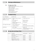
Page 11: ...function in the device or the electronic control Connect the power cord Switch on the unit Replace the fuse Loctite Service Not enough suction capacity Filter 3 is clogged or worn Air passage is blocked Replace filter Check air inlet and outlet for obstacles Bad filtration Filter is clogged The filter is not correctly assigned Replace filter Check the seat of the filter and make necessary correcti...

Page 12: ...chlüsse 15 3 Technische Daten 16 4 Montage 17 4 1 Umgebungs und Betriebsbedingungen 17 4 2 Anschließen des Gerätes 17 4 3 Anschließen des Saugschlauchs 17 4 4 Anschließen des Saugarms 17 5 Betrieb 18 6 Reinigung und Wartung 19 6 1 Allgemeine Anweisungen 19 6 2 Berechnen der Lebensdauer des Filters 19 6 3 Entsorgung 19 6 4 Auswechseln des Filters 20 7 Fehlersuche 20 8 Zubehör und Ersatzteile 20 Dec...

Page 13: ...e fett gedruckten Zahlen im Text beziehen sich auf die entsprechende Positionsnummer in der Abbildung auf Seite 15 Der Punkt hebt einen Handlungsschritt hervor Handlungsschritte in Abbildungen sind durch schwarze Pfeile dargestellt 1 2 Lieferumfang 1 Luftfilter System LAS 250 Typ Nr 97603 Bestellnr 527595 1 Netzkabel 1 Bedienungsanleitung Bedingt durch die technische Entwicklung können Abbildungen...

Page 14: ... spannungsführender Teile kommen Vor jedem Gebrauch Netzkabel und Gerät kontrollieren Ein beschädigtes Netzkabel oder Gerät nicht in Betrieb nehmen Das beschädigte Netzkabel durch ein neues ersetzen Sicherheitseinrichtungen dürfen nicht entfernt umgangen oder deaktiviert werden Dies kann zur Beschädigung des Gerätes führen und ist daher verboten Das Luftfilter System darf nie ohne Filter verwendet...

Page 15: ...g des Filters 3 2 2 Anzeigen Bedienelemente und Anschlüsse 1 2 Saugleitungsflansch Abnehmbare Haube 8 Stufenlos regulierbare Luftstromsteuerung 3 Filter 9 Netzschalter 4 Schnappverschluss 10 Saugschlauch nicht dargestellt 5 Schalldämpferkassette mit 11 Der Saugarm nicht dargestellt 6 rückseitigem Luftauslass Gehäuse mit integriertem Lüfter 10 und 11 sind Zubehör und müssen separat bestellt werden ...

Page 16: ...x Luftstrom 450 m h Konstanter Luftstrom 250 m h bei 2 200 Pa Max Unterdruck 2 600 Pa Abmessungen Breite x Höhe x Tiefe 370 mm 780 mm 500 mm Umgebungstemperatur bei Betrieb 10 C bis 45 C Lagertemperatur 5 C bis 55 C Relative Luftfeuchtigkeit bei Lagerung Max 50 Gewicht ca 40 kg Lärmpegel 52 dB A Abmessungen ...

Page 17: ...Netzkabel am Gerät anschließen 4 3 Anschließen des Saugschlauchs Das Luftfilter System kann über zwei Y Splitter mit vier Saugschläuchen für maximal vier Arbeitsplätze ausgestattet werden Die Y Splitter müssen vor den Saugschläuchen montiert werden Sie sind separat zu bestellen Saugschlauch 10 auf Saugleitungs Flansch 1 oder auf den Y Splitter stecken 4 4 Anschließen des Saugarms Saugleitungsflans...

Page 18: ...l anschließen Gerät einschalten Luftstrom einstellen 8 Außerbetriebnahme Bei kurzen Stillstandszeiten Luftstrom auf 0 stellen 8 Bei längeren Stillstandszeiten Gerät ausschalten Netzkabel abziehen Erneute Inbetriebnahme Nach kurzen Stillstandszeiten Richtige Position der Saugschläuche 10 prüfen Luftstrom wieder einstellen 8 Nach längeren Stillstandszeiten Richtige Position der Saugschläuche 10 prüf...

Page 19: ... Heptan Es wird nicht vom Filter aufgenommen Für eine Standard Klebstoffanwendung kann von einer Freisetzung an Produktdämpfen von deutlich kleiner als ein Prozent der eingesetzten Klebstoffmenge ausgegangen werden Die Filterkassette hätte demnach eine Standzeit die dem Verwendungs Zeitraum von mehr als 100 200 Liter Klebstoff entspricht Wie bereits erwähnt stellen umgebungsabhängige Faktoren eine...

Page 20: ...eschaltet Sicherung defekt Störung im Gerät oder der elektronischen Steuerung Netzkabel anschließen Gerät einschalten Sicherung tauschen Loctite Service Saugleistung zu schwach Filter 3 verstopft oder verschlissen Luftleitung blockiert Filter auswechseln Lufteinlass und auslass auf Gegenstände überprüfen Schlechte Filterung Filter verstopft Filter nicht richtig montiert Filter auswechseln Sitz des...

Page 21: ... Diese Erklärung ist ungültig wenn es irgendwelche Änderungen gibt die nicht von Henkel genehmigt worden sind Declaration of Conformity The Manufacturer according to the EC regulations Henkel AG Co KGaA Standort München Gutenbergstr 3 D 85748 Garching declares that the unit designated in the following is as a result of its design and construction in accordance with the European regulations harmoni...

Page 22: ...Henkel AG Co KGaA Standort München Gutenbergstraße 3 D 85748 Garching b München Henkel AG Co KGaA 2009 C ...

Reviews: