background image

Products and functions

YarnMaster PRISMA

www.loepfe.com

15

3.3

Functionality

P clearing

n

Clearing and classification of synthetic foreign
matter (PP/PE/PES)

OffColor (option)

n

OffColor

– dark
– light

F clearing

n

Clearing and classification of foreign matter

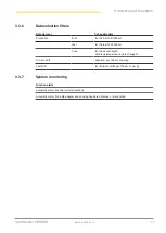
– dark
– light

n

Organic Filter

n

Clearing of foreign matter clusters

– dark
– light

LabPack (Option)

n

SFI/D clearing and classification

– SFI/D short
– SFI/D long

n

SFI surface index

n

Imperfections

– IPI and IPI alarm

DM clearing

n

NSLT clearing

n

NSLT cluster clearing

n

Yarn count clearing

n

Short count clearing

n

Core clearing

– OffCentric Core
– Missing core

n

Splice clearing and classification

n

OffLimit alarm

n

Class alarm

n

Detection of OffStandard bobbins

PRISMA DM

PRISMA DMF

PRISMA DMFP

Summary of Contents for YarnMaster PRISMA

Page 1: ...Operating instructions YarnMaster PRISMA 51318003_en Original manual Version 1 0 12 2021 ...

Page 2: ......

Page 3: ...ges This Instruction Manual is protected by copyright Reproduction of this Instruction Manual in whole or in part dissemination to third parties and use and or disclosure of its contents without the written permission of Loepfe Brothers Ltd is prohibited except for internal purposes is a registered trademark of Loepfe Brothers Ltd in Switzerland and or in other countries 2021 Loepfe Brothers Ltd S...

Page 4: ......

Page 5: ... 1 Loepfe Central Unit LZE 12 3 1 2 Spindle adapter 12 3 1 3 Sensing head 13 3 2 Scope of delivery 14 3 3 Functionality 15 3 3 1 DM clearing 16 3 3 2 LabPack Option 17 3 3 3 F clearing 18 3 3 4 OffColor option 18 3 3 5 P clearing 18 3 3 6 Data selection filters 19 3 3 7 System monitoring 19 4 Startup 20 4 1 Installation 20 4 2 Startup after an upgrade or software update 21 4 3 Startup after an int...

Page 6: ...Packing transport and storage 42 7 1 Packing the devices 42 7 2 Transport inspection 42 7 3 Storage of devices 42 8 Technical Data 43 8 1 System 43 8 2 Loepfe Central Unit LZE 43 8 3 Spindle adapter 44 8 4 Sensing head 44 9 Dismantling and Removal 45 9 1 Dismantling 45 9 2 Removal 45 9 2 1 Hazardous Waste 45 10 Spare parts and accessories 46 10 1 Non original spare parts or non approved accessorie...

Page 7: ... This document is intended exclusively for the operators The descriptions require qualified personnel trained by the manufacturer The descriptions do not replace product training 1 1 3 Note Information symbol This symbol indicates additional information for the user Illustrations in the document The user interface screen copies illustrations in these operating instructions are examples and make no...

Page 8: ...as an operator who meets the necessary training and knowledge requirements and is authorized to perform the associated task 2 3 1 Qualified personnel The device and software manufacturer defines qualified personnel as follows n Foreman The foreman can guide the operator and specify settings and configurations for devices and software n Electrician The electrician is responsible for installing the ...

Page 9: ...ly hazardous situation that will lead to death or severe injury WARNING Indicates a potentially hazardous situation that can lead to death or severe injury CAUTION Indicates a potentially hazardous situation that can lead to minor or moderate injury NOTE Indicates a potentially hazardous situation that can lead to property damage 2 4 1 Description of symbol Warning symbols General warning symbol E...

Page 10: ...bols Switched on mobile phones not permitted Operation with long hair not permitted Instruction symbols Disconnect power plug Disconnect before maintenance or repair disconnect power supply Ground before using ESD symbol Electrostatically sensitive components ...

Page 11: ...of injury and property damage through custom modifications to the yarn clearer system 4Only authorized service technicians may perform installation and operation of the yarn clearer system or individual system parts or perform upgrades 2 5 1 Safety features is integrated into a winder and has no additional safety features For more information about safety features like the emergency off switch see...

Page 12: ...ombined with the MillMaster TOP data evaluation and administration system 3 1 1 Loepfe Central Unit LZE LZE 6 central unit The central unit consists of the following components n Computer n Touchscreen display n USB port n Yarn clearer software Functions n Communication with sensing heads n Yarn clearing control and monitoring n Processing logging and storage of process and quality data 3 1 2 Spin...

Page 13: ...rs to detect yarn diameter yarn mass and foreign matter n Integrated evaluation electronics n Yarn clearer software 1 2 3 5 7 8 4 6 Prisma sensing head 1 M sensor for detecting yarn mass capacitive 5 P sensor for detecting synthetic foreign matter triboelectric 2 F sensor for detecting foreign matter optical RGB 6 Side limiters 3 D sensor for detecting yarn diameter optical 7 Test button Reset n C...

Page 14: ...ign matter Yarn count range TK YM PRISMA DM Threshold range coarse Nm 4 0 10 0 Nec 2 4 5 9 Threshold range fine Nm 430 540 Nec 255 320 TK YM PRISMA DMF TK YM PRISMA DMFP Threshold range coarse Nm 7 0 10 0 Nec 4 1 5 9 Threshold range fine Nm 430 540 Nec 255 320 3 2 Scope of delivery The following components are included in the scope of delivery n sensing head n Loepfe Central Unit LZE with touchscr...

Page 15: ...rganic Filter n Clearing of foreign matter clusters dark light LabPack Option n SFI D clearing and classification SFI D short SFI D long n SFI surface index n Imperfections IPI and IPI alarm DM clearing n NSLT clearing n NSLT cluster clearing n Yarn count clearing n Short count clearing n Core clearing OffCentric Core Missing core n Splice clearing and classification n OffLimit alarm n Class alarm...

Page 16: ... 10 0 Threshold value for fault length ID 0 4 0 128 cm Thin Diameter threshold value ID 0 4 0 3 0 96 Threshold value for fault length ID 0 4 1 0 128 cm Yarn count channel Mass deviation ID 0 4 3 50 Threshold value for fault length ID 0 4 10 50 m Short count channel Mass deviation ID 0 4 3 50 Threshold value for fault length ID 0 4 1 10 m OffLimit alarm Monitoring of textile and technical events 5 ...

Page 17: ...eshold value per 1000 m Neps Diameter threshold value 1 80 Thick Diameter threshold value 1 30 1 80 Thin Diameter threshold value 0 8 Count of the most frequent yarn faults by diameter threshold value per m Small Positive deviation diameter threshold value 1 20 1 30 Negative deviation diameter threshold value 0 83 0 8 Count of the most frequent yarn faults by length threshold values per 1000 m 4 y...

Page 18: ...ult length 0 12 8 cm F clusters Detection of 70 foreign matter classes each n dark n light Threshold value for fault length 1 80 m Maximum foreign matter count based on the monitoring length specified in the set tings 1 9999 3 3 4 OffColor option OffColor Limit n dark n light Intensity 0 1 10 1 10 Threshold value for fault length 0 2 50 m 3 3 5 P clearing P matrix Intensity of charge P ID 0 7 0 10...

Page 19: ... km Last for the last 100 1000 km Cone for the wound length data is deleted when cone is changed Current shift absolute per 100 km or per kg Last shift for the last 5 shifts per 100 km or per kg 3 3 7 System monitoring Function alarm Automatic alarm if central unit malfunctions Automatic alarm if spindle adapter and sensing head are defective or malfunction ...

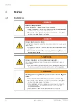
Page 20: ...from the power supply before removing the covers or opening the side panels WARNING Danger from incorrect installation and operation Risk of injury and property damage through custom modifications to the yarn clearer system 4Only authorized service technicians may perform installation and operation of the yarn clearer system or individual system parts or perform upgrades WARNING Working on running...

Page 21: ...er manufacturer training is provided by authorized service technicians 4 2 Startup after an upgrade or software update To ensure safe operation of the yarn clearer system all upgrades and software updates must be performed by authorized service technicians 4 3 Startup after an interruption in operations After an interruption in operations e g as the result of a power outage a warm start will be in...

Page 22: ... 24 V DC LZE 6 Power supply 24 V DC Variant 2 External power supply 90 264 V AC Variant 3 External power supply 24 V DC LZE 6 Faceless Ethernet con nection crossover ca ble Savio control unit Loepfe 2 wire bus L2B Spindle computer machine Spindle adapter yarn clearer Loepfe 2 wire bus L2B Sensing head ...

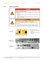
Page 23: ...s or opening the side panels WARNING Danger from incorrect installation and operation Risk of injury and property damage through custom modifications to the yarn clearer system 4Only authorized service technicians may perform installation and operation of the yarn clearer system or individual system parts or perform upgrades Front panels USB 2 0 interface USB port n For data transfer of settings a...

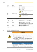
Page 24: ... the connection with the Savio control unit LAN 2 RJ45 Network connection dynamic IP DHCP USB 3 0 USB port 4x 4 6 Installing the sensing head WARNING Working on running machines poses a risk of severe physical injury 4Switch off machines and wait until they have come to a complete stop 4Work on electrical components may only be performed when the system is switched off and disconnected from power ...

Page 25: ...e integrated spindle adapter 8 Replace the spindle cover PIN Loepfe label max A 10 7 V 0 5 V 0 25 9 5 V 0 5 V 0 20 8 54 V 8 10 0 15 7 GND 6 SPINDLE_STATUS 5 SPINDLE_RXD 4 SPINDLE_TXD 3 LoepfeBus_A 2 LoepfeBus_B 1 SPINDLE_DRUM_PULSE 4 7 Software installation wizard 4 7 1 Set basic settings The default settings can be modified later at any time The installation wizard walks you through the basic set...

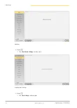
Page 26: ...Startup 26 www loepfe com YarnMaster PRISMA Welcome 2 Press ð The Import System Settings window opens Import system settings 3 Press ð The Basic Settings window opens ...

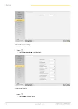
Page 27: ...p YarnMaster PRISMA www loepfe com 27 Basic Settings 4 Select the Machine type 5 Press ð The Alarm Messages Setting window opens Alarm Messages Setting 6 Press ð The Default Data Capture Settings window opens ...

Page 28: ...Startup 28 www loepfe com YarnMaster PRISMA Default Data Capture Settings 7 Press ð The Default Group Settings window opens Default Group Settings 8 Press ð The Network window opens ...

Page 29: ...Startup YarnMaster PRISMA www loepfe com 29 Network 9 Press ð The Ethernet 1 window opens Ethernet1 10 Press ð The Ethernet 2 window opens ...

Page 30: ...Startup 30 www loepfe com YarnMaster PRISMA Ethernet2 11 Press ð The Software Options window opens Software Options 12 Press ð The Shift Report Configuration window opens ...

Page 31: ...rtup YarnMaster PRISMA www loepfe com 31 Shift Report Configuration 13 Press ð The Done window opens Done ð The basic settings have been set 14 Press ð The installation wizard closes ð The system restarts ...

Page 32: ...ibited cleaning agents NOTE Damage to the sensors due to the use of prohibited cleaning agents No warranty is given for damage caused by using prohibited cleaning agents Only use permitted and recommended cleaning agents 4Prohibited cleaning agents include ð all alcohols such as methanol and ethanol ð all gasolines such as car or aviation gasoline and ð other substances such as benzene toluene ace...

Page 33: ...s in cleaning agents After the sensor s measurement channel has been cleaned it is recommended to adjust the spindle or group When using kerosene antistatic oils dyes and other chemical additives such as poligomers or titanium dioxide the sensor area must be cleaned at shorter intervals Prerequisite ü Cotton swabs are included ü Sensing head cleaner is included 1 Use dry or moistened cotton swabs ...

Page 34: ...ctrostatically sensitive components NOTE Danger to electronic components due to electrostatic discharge Improper handling of electronic components can cause damage that leads to complete failure or sporadic errors 4Observe the general ESD protection measures when installing and repairing the product 4Only touch the edges of the printed circuit boards 4Do not touch the printed circuit board and con...

Page 35: ...Maintenance YarnMaster PRISMA www loepfe com 35 8 Insert covers at the corresponding spindle 9 Switch on the power supply to the spindle 10 Start the spindles ...

Page 36: ...vents further use of the LZE and cannot be confirmed Last messages Last message 1 Press the Message display button ð The last 20 messages are displayed Messages window 6 1 2 Messages that require action The following symbols can be selected in the Messages window and are described in the table Symbol Description Symbol Description Indicates that there are messages Confirm all messages Delete all m...

Page 37: ...Troubleshooting YarnMaster PRISMA www loepfe com 37 1 Press ð The Messages that require action window opens ð A message that requires action must be confirmed Troubleshooting 36 ...

Page 38: ... for detect ing yarn diameter outside of tolerance Clean optics Adjust single spindle Press TK reset test button Unplug TK plug in again after 10 s Replace TK Condition D optics outside of tolerance Check D sensor D Health value too low 100 is optimal Clean optics Adjust single spindle Replace TK Condition F optics outside of tolerance Check F sensor F health value too low op timum is 100 Clean op...

Page 39: ...n group mean value Check function and setting of spindle splicer 6 2 Technical Alarm Flashing display means alarm n the corresponding cause of the alarm is displayed on the sensing head n the respective spindle is stopped n the faulty yarn is automatically removed from the cross wound bobbin max 80 m n the respective bobbin is ejected depending on the machine setting and the machine type check the...

Page 40: ...asurement channel AL 24 Yarn is in the M measuring channel 3 consecutive M sensor ECR values deviate 5 from the previous average monitoring active after 5 suc cessful ECRs Clean measurement channel AL 25 Yarn is in the F measuring channel 3 consecutive F sensor ECR values deviate 5 from the previous average monitoring active after 5 suc cessful ECRs Clean measurement channel Repeat adjustment Disp...

Page 41: ...fe reel missing 200 ms Reset alarm 5 s TK Press re set test button Replace TK AL 45 Sensing head in compatible At least one TC hardware com ponent with installed firmware not compatible Reset alarm 5 s TK Press re set test button Replace TK AL 46 Knife not available Knife available but not config ured in Flash or CPLD or loose contact connector from knife Reset alarm 5 s TK Press re set test butto...

Page 42: ...tective packaging 7 2 Transport inspection Check the delivery for completeness and transport damage upon receipt ü Transport damage is discovered during the receiving inspection 1 Notify deliverer 2 Create damage report 3 Inform supplier Claims for damages must take place within the valid complaint periods 7 3 Storage of devices The following storage conditions must be observed for the devices and...

Page 43: ...le adapter for each spindle Sensing head 1 Sensing head for each spindle Applicable for Staple yarn made of natural and synthetic fibers Ambient conditions Operating temperature 0 50 C Storage temperature 0 60 C Transport temperature 25 70 C Humidity relative max 95 rH not condensing 8 2 Loepfe Central Unit LZE LZE 6 Central unit Screen Touchscreen with LCD color display User interface Multilingua...

Page 44: ...Winding speed up to 2200 m min 8 4 Sensing head Safety EMC EN 61010 1 2010 10 A1 2019 EN 61326 1 2012 07 Compressed air connection max 7 5 bar without oil TK Type Threshold range coarse Threshold range fine DM Nm 4 0 10 0 Nec 2 4 5 9 Nm 430 540 Nec 255 320 DMF Nm 7 0 10 0 Nec 4 1 5 9 Nm 430 540 Nec 255 320 DMFP Nm 7 0 10 0 Nec 4 1 5 9 Nm 430 540 Nec 255 320 ...

Page 45: ...operly and in accordance with the usual national environmental protection regulations 9 2 1 Hazardous Waste Electronic components Possible environmental and property damage due to improper disposal of electrical and electronic components assemblies If you need to dispose of these products please observe the following n Electrical and electronic components and assemblies as well as batteries and ca...

Page 46: ...ystem 4Only use original spare parts or accessories approved by Gebrüder Loepfe AG Gebrüder Loepfe AG does not accept liability for damage resulting from the use of spare parts replacement parts conversion parts not supplied by Gebrüder Loepfe AG 10 2 Order Information All listed spare parts can be ordered through the local representative or the service of To prevent incorrect deliveries and delay...

Page 47: ...85000 Power supply cable AC 24 V 50307000 Power supply cable TAITAN 24 V 46416000 Power supply cable SMARO ISPERO 115 230 V 46390000 Bus adapter cable SOP 44959000 Spindle adapter Spindle adapter QPRO Spindle adapter 21Cspindle Spindle adapter SOP Spindle adapter AC Spindle adapter AC338 Spindle adapter SMARO ISPERO 50328000 50330000 50155000 50274000 50276000 50233000 TK YM Prisma sensing head Mu...

Page 48: ...5 ACX5 TK YM Prisma DM TK YM Prisma DMF TK YM Prisma DMFP 51334000 51261000 51262000 Schalfhorst AC6 ACX6 TK YM Prisma DM TK YM Prisma DMF TK YM Prisma DMFP 51335000 51263000 51264000 TK YM Prisma Knife 50033030 TK YM Prisma Thread Guide Plate 2 x SR HDR TORX M2 5X12 51212000 17373900 Standard side limiters Half moon side limiters 1 x SR LZYL TORX KOMBI M2 5X6 51327000 51389000 17186900 P Sensor Y...

Page 49: ...Gebrüder Loepfe AG 8623 Wetzikon Switzerland Phone 41 43 488 11 11 Fax 41 43 488 11 00 service loepfe com www loepfe com 51318003_en ...

Reviews: