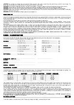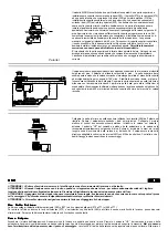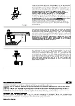
WARNING !
your windlass is not designed as a strong point to fasten your anchor rode (chain or rope) to when the boat is laying on it’s anchor and surging. The
anchor rode must be fastened to a strong point such as mooring cleat, bollard or chain storage.
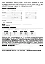
WARNING !
do not exceed a pulling load more than the rating of your windlass. The vessel’s engine be running and used to assist in the anchor recovery.
WARNING !
always install the properly rated circuit breaker to protect the electric plant and electric motor from overheating and damages.
WARNING !
when not in use be sure to keep the anchor windlass circuit switch in the
Off
position to prevent accidental engagement of the windlass.
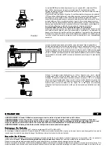
WARNING !
always keep your hands, feet and fingers clear of an operating windlass. If a jam occurs use extreme caution and turn off the windlass circuit before
attending to clearing the anchor rode.
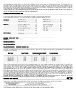
WARNING !
do not use the windlass for different purposes it was designed for.
W
W
W
W A
A
A
A R
R
R
R R
R
R
R A
A
A
A N
N
N
N T
T
T
T Y
Y
Y
Y
Lofrans' S.r.l. warrants its products for a period of one (
1
) year from the date of purchase against defects in materials or workmanship , under normal use and
service. Any part which proves to be defective in normal usage during that one year period will be repaired or replaced by Lofrans’. This warranty is subjected to
the conditions listed below.
Lofrans' liability shall be limited to repair or replacement of the part defective in materials or workmanship.
Lofrans shall not be liable in any way for failures due to use of products in applications for which they are not intended , improper installation , misuse ,incorrect
maintenance , corrosion , normal wear and tear , discoloration and unauthorised alteration of the product, conditions that exceed the product 's performance
specifications.
The claim of warranty must be promptly notified in writing , to Lofrans or Lofrans’ authorised distributor, providing proof of purchase. Repair will be under taken
upon return of the defective part , freight prepaid to Lofrans or Lofrans authorised distributor. Lofrans or its authorised distributor will not be responsible for any
shipping charges or labour cost associated with any warranty claims. Lofrans shall not be liable for consequential damages to yachts , equipment or other
property or persons due to use or installation of Lofrans equipment. Implied warranties are limited to the life of this warranty. All incidental and/or consequential
damages are excluded from this warranty. Some states do not allow limitations on how long an implied warranty lasts or the exclusion or limitation of incidental
or consequential damages , so the above limitation or exclusions may not apply to you.
Lofrans’ reserves the right to disclaim the warranty in case the windlass is controlled by not suitable electric accessories and/or in case of non
installation of a proper circuit breaker on the windlass electric line.
M
M
M
MO
O
O
OD
D
D
DE
E
E
EL
L
L
L C
C
C
CL
L
L
LA
A
A
AS
S
S
SS
S
S
SIIIIF
F
F
FIIIIC
C
C
CA
A
A
AT
T
T
TIIIIO
O
O
ON
N
N
N
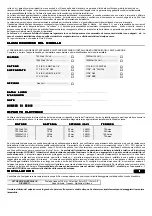
FOR YOUR OWN SAFETY PLEASE READ THESE INSTRUCTIONS BEFORE INSTALLING OR OPERATING YOUR WINDLASS.
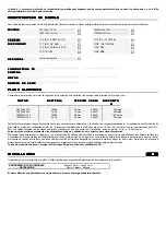
Fill in this form to obtain a complete classification of the installed model.
M
M
M
M O
O
O
O T
T
T
T O
O
O
O R
R
R
R
700 Watt 12 Volt ...............................
700 Watt 24 Volt ...............................
1000 Watt 12 Volt .............................
1000 Watt 24 Volt .............................
C
C
C
C H
H
H
H A
A
A
A IIII N
N
N
N
∅
6 ISO - 6 DIN 766 - 1/4”
∅
10 ISO - 10 DIN 766
A
A
A
A V
V
V
V A
A
A
A IIIIL
L
L
L A
A
A
A B
B
B
B L
L
L
L E
E
E
E
∅
7 ISO - 1/4” G40
∅
3/8” - 3/8” DIN 766
∅
8 ISO - 8 DIN 766 - 5/16”
∅
3/8” G40
∅
5/16” G40
∅
3/8” BBB
O
O
O
O P
P
P
P T
T
T
T IIII O
O
O
O N
N
N
N A
A
A
A L
L
L
L
Free Fall version ................................
P
P
P
PU
U
U
UR
R
R
RC
C
C
CH
H
H
HA
A
A
AS
S
S
SE
E
E
E D
D
D
DA
A
A
AT
T
T
TE
E
E
E &
&
&
&
P
P
P
P L
L
L
L A
A
A
A C
C
C
C E
E
E
E
...........................................................
...........................................................
N
N
N
N O
O
O
O T
T
T
T E
E
E
E S
S
S
S
...........................................................
...........................................................
S
S
S
SE
E
E
ER
R
R
RIIIIA
A
A
AL
L
L
L N
N
N
NU
U
U
UM
M
M
MB
B
B
BE
E
E
ER
R
R
R
...........................................................
E
E
E
EL
L
L
LE
E
E
EC
C
C
CT
T
T
TR
R
R
RIIIIC
C
C
C P
P
P
PL
L
L
LA
A
A
AN
N
N
NT
T
T
T
Check that the motor tension corresponds to the electric plant on board. The following table shows the suggest minimum battery feeding the windlass , the
minimum suggested cable section and the proper circuit breaker to install on the power line.
M
M
M
M O
O
O
O T
T
T
T O
O
O
O R
R
R
R
B
B
B
B A
A
A
A T
T
T
T T
T
T
T E
E
E
E R
R
R
R Y
Y
Y
Y
C
C
C
CA
A
A
AB
B
B
BL
L
L
LE
E
E
ES
S
S
S S
S
S
SE
E
E
EC
C
C
CT
T
T
TIIIIO
O
O
ON
N
N
N
C
C
C
CIIIIR
R
R
RC
C
C
CU
U
U
UIIIIT
T
T
T B
B
B
BR
R
R
RE
E
E
EA
A
A
AK
K
K
KE
E
E
ER
R
R
R
700 Watt 12 V
100 Ah
25 mm_
3 AWG
70 Amps
700 Watt 24 V
70 Ah
16 mm_
4 AWG
35 Amps
1000 Watt 12 V
150 Ah
35 mm_
2 AWG
100 Amps
1000 Watt 24 V
90 Ah
25 mm_
3 AWG
70 Amps
If the windlass is fed by an inferior battery , the performances will be worse and the battery will be subject rapidly to wear and tear. We recommend to use
excellent quality cables , insulated and heat resistant. It is important underline the cables section should be increased of 30% - 50% approx., if the length of the
extended cable , positive and negative , is greater than 10 mts. or 29' length. The cables connected to the electric controls , shown on the wiring diagram as a
thin line , should have a section of 1.5 mm_ or 16 AWG approx.
Circuit breaker informations referring only to LOFRANS’ circuit breaker so they could be incorrect for other circuit breakers.
The circuit breaker protects from very dangerous short circuits , protects the windlass motor , avoiding damages due to anomalous absorption and interrupts the
tension , when desired. The circuit breaker must be installed in a dry , accessible and visible position . For safety reasons we recommend that the windlass and
remote controls are isolated during navigation and reactivated when anchoring. Install the control box preferably in a dry place on board. We recommend to
install at least two remote controls to drive the windlass in case one of them gets damaged.
For protection of electric remote controls, it will be necessary to install a circuit breaker of 5 Ampere.
We recommend You to use original LOFRANS' components only , which are designed for sea water purpose. LOFRANS equipment conforms
to European Directives, products are CE approved.
IIIIN
N
N
N S
S
S
S T
T
T
T A
A
A
A L
L
L
L L
L
L
L A
A
A
A T
T
T
T IIIIO
O
O
O N
N
N
N
G
G
G
G B
B
B
B
Check if the windlass is complete in every parts. If any parts is missing or damaged , please contact your dealer.


