background image

TOOLS AND MATERIALS

Drill 

 9 mm (3/8”), Spanner 10 mm A/F - 13 mm A/F

REQUIREMENTS

Jig Saw, Power Drill , Silicone Sealant

The electric motor of the windlass is able to operate under spray conditions ; however , if submerged , it could be irreparably damaged.

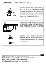
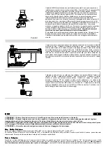
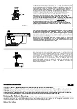
The AIRON model is made by a top part , including drum (274) , gipsy (276) and base
(290), and an under deck part , the gearbox (305) and electric motor (315).
Check  there are no  under and  over  deck  obstructions. Be sure there is ample room to
enable you to use the handle (272). In order to facilitate maintenance operations Lofrans
suggest to install the  windlass on a removable panel  fixed on the  deck by bolts. Standard
maximum deck thickness is 40 mm (1  9/16”) ; for deck exceeding this thickness , please
consult your dealer. If  the  deck is too  thin or inadequate , it will be necessary to use a
backing  pad  (plywood , timber ) of sufficient dimensions to  spread  the  stress  imposed
during recovery  of  chain. 

To  avoid  electrolysis problems  do not  use stainless steel

pad as backing pad.

    For  boats of steel or aluminium , it is very important that top and

under deck parts are insulated  from  the  deck  with a non  conductive  gasket. It is essential
that top and  under deck parts are fitted parallel ; in some cases a mounting pad  may be
necessary.  Incorrect  alignment  may result in extra  load being imposed on  the  motor
causing loss of power and overheating with excess current consumption.

400 mm

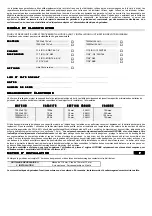
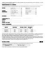
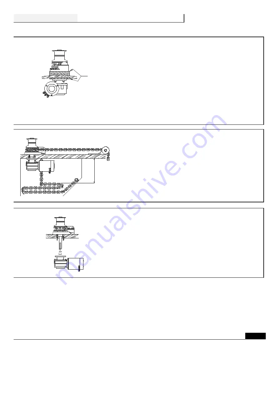
The windlass must be placed where the chain locker has the max depth.  The  top  part  must
be  located so that the chain runs  parallel to  the  deck  and  turn  around  the  gipsy  with a
rotation of 180° approx. Ensure the chain locker is of sufficient capacity to store all the chain
and leave a minimum of   400 mm (16") between  underside of the  deck  and the top of the
heaped chain. When  the position of the windlass  has been  set , drill  the  necessary holes ,
using the  template we supply. Separate  top and under deck part loosening the  nuts  (227)
from the studs (292) and seal , using a good quality silicone sealant , the bottom  of  the base
and around the studs.  Place the top part on the deck.

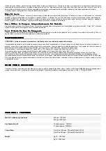
Under  deck part may be oriented in the  most  suitable of four positions. Check that the
electric motor does not obstruct the run of the chain into the locker. Join the under  deck part
to the top part inserting the key (284) of the main shaft into the key way of the gearbox. Tight
the  nuts on the  studs. Join the  cables to the  electric  motor.   Introduce the chain into the
gipsy , operate  the  "UP"  switch of the foot switch  or remote control and the chain will
automatically be fed  into  your  locker.  Take care to keep hands and  feet  well  clear  of
incoming chain. If  the windlass runs in wrong direction , change over  M1 and M2 cables  at
the control box.
After   using    the  windlass , we  strongly  recommend that the nuts  are checked again to
ensure they are well tightened.

O

O

O

O P

P

P

P E

E

E

E R

R

R

R A

A

A

A T

T

T

T IIIIO

O

O

O N

N

N

N S

S

S

S

G

G

G

G B

B

B

B

WARNING ! = Do not approach with hands or feet near the gipsy and chain , when operating.
WARNING ! = When the windlass is not in use or before use the handle , turn off the windlass at the main switch .
WARNING ! = Engage the chain stopper after anchoring. Windlass must not be used as sole means securing anchor in bow fitting.  Anchors
should be independently secured to prevent accidental release .
WARNING ! = Be sure the clutch and the chain stopper are  well engaged before boating.

G

G

G

Giiiip

p

p

ps

s

s

sy

y

y

y     C

C

C

Cllllu

u

u

uttttc

c

c

ch

h

h

h     O

O

O

Op

p

p

pe

e

e

errrra

a

a

attttiiiio

o

o

on

n

n

n

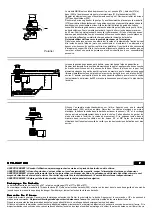
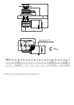
Gipsy is connected at the main shaft (282) or (287)  by a clutch , items  (275 and 277) or (286 and 277).

Parallel

Summary of Contents for AIRON Series

Page 1: ...g 2 Operations pg 4 Exploded diagram pg 18 Model classification pg 2 Maintenance pg 4 Parts List pg 19 Electric plant pg 2 Ordering spare parts pg 4 Lofrans sales organization pg 20 I Informazioni sul...

Page 2: ...ONS BEFORE INSTALLING OR OPERATING YOUR WINDLASS Fill in this form to obtain a complete classification of the installed model M M M M O O O O T T T T O O O O R R R R 700 Watt 12 Volt 700 Watt 24 Volt...

Page 3: ...etween underside of the deck and the top of the heaped chain When the position of the windlass has been set drill the necessary holes using the template we supply Separate top and under deck part loos...

Page 4: ...and periodic maintenance operation is essential for the best efficiency of your windlass At least once every month remove the salt layer which forms periodically on the outer casting to avoid electrol...

Page 5: ...M M MP P P PI I I IA A A AN N N NT T T TO O O O E E E EL L L LE E E ET T T TT T T TR R R RI I I IC C C CO O O O Verificare che la tensione del motore elettrico del salpa ancore corrisponda a quella d...

Page 6: ...cima del mucchio di catena raccolta Collegare la parte inferiore a quella superiore infilando la chiavetta 284 dell albero nel riduttore Fissare il salpa ancore serrando i dadi sui prigionieri Collega...

Page 7: ...strarre 277 Pulire e controllare tutti i particolari affinch non presentino inizi di corrosione e ingrassare il filetto dell albero con grasso marino In caso di periodi di lunga inattivit del salpa an...

Page 8: ...l alimentation M M M M O O O O T T T T E E E E U U U U R R R R C C C CA A A AP P P PA A A AC C C CI I I IT T T T S S S SE E E EC C C CT T T TI I I IO O O ON N N N C C C C B B B BL L L LE E E ES S S S...

Page 9: ...ectriques au moteur lectrique Introduire la cha ne dans le barbotin actionner le poussoir UP et le cordage cha ne rentrera automatiquement dans le puits cha ne Faites attention de garder les pieds et...

Page 10: ...pas de vis Si apr s une longue p riode d inactivit le moteur tourne lentement nous vous conseillons de v rifier les charbons et de les remplacer si n cessaire Il est fortement recommand d enlever le g...

Page 11: ...E E ER R R RI I I IE E E E K K K KA A A AB B B BE E E EL L L LQ Q Q QU U U UE E E ER R R RS S S SC C C CH H H HN N N NI I I IT T T T T T T T S S S S I I I I C C C C H H H H E E E E R R R R U U U U N...

Page 12: ...mm zwischen Decksunterseite und der aufgestapelten Kette frei bleibt Beim Verschrauben der Unter und Oberdeckeinheit beachten Sie da der Keil auf der Hauptwelle sauber in die Getriebeinheit eingef hrt...

Page 13: ...ernen Sie Teil 276 und 277 Flachversion mit dem Notgriff l sen Sie Teil 285 entfernen Sie Teil 286 L sen Sie Teil 217 entfernen Sie Teil 288 und 289 ziehen Sie Teil 276 und 277 heraus Reinigen und ber...

Page 14: ...Y Y Y Y U U U U N N N N T T T T O O O O R R R R 700 Watt 12 V 100 Ah 25 mm_ 3 AWG 70 Amps 700 Watt 24 V 70 Ah 16 mm_ 4 AWG 35 Amps 1000 Watt 12 V 150 Ah 35 mm_ 2 AWG 100 Amps 1000 Watt 24 V 90 Ah 25 m...

Page 15: ...enar toda la cadena y quede un espacio m nimo de 400 mm entre la cubierta y la parte superior de la cadena estibada Unir la parte inferior y superior colocar la chaveta 284 del eje principal en la ent...

Page 16: ...ordar que en fondeos profundos el esfuerzo ser grande M M M MA A A AN N N NT T T TE E E EN N N NI I I IM M M MI I I IE E E EN N N NT T T TO O O O ATENCION Antes de empezar desconectar el molinete y sa...

Page 17: ...mm 175 min 20 max 40 137 85 114 215 61 5 240 700 W 242 1000 W 150 94 700 W 114 1000 W inches 6 7 8 min 11 16 max 1 9 16 5 3 8 3 3 8 4 1 2 8 7 16 2 7 16 9 7 16 700 W 9 9 16 1000 W 5 15 16 3 11 16 700 W...

Page 18: ......

Page 19: ......

Page 20: ...aft 1 283 Key 6x6x80 Kit C 1 284 Key 8x7x60 Kit C 1 285 Gipsy cap 1 286 Cone clutch 1 287a Main shaft for gipsy type a b c 1 287b Main shaft for gipsy type d e f g h 1 288a Stripper for gipsy type a b...

Reviews: