background image

3

Carbide Cutter OM

Owner Information

Thank you for your decision to purchase a Carbide Cutter 
from Loftness. To ensure maximum performance of your 
machine,  it  is  mandatory  that  you  thoroughly  study  the 
owner’s manual and follow its recommendations. Proper 
operation and maintenance are essential to prevent injury 
or damage and to maximize machine life.

The  Loftness  Carbide  Cutter  is  an  effective,  reliable 
machine  used  for  maintaining  grass,  weeds,  brush  and 
trees.  Efficiently  cuts  and  mulches  up  to  6"  diameter 
material. Intermittently cuts larger diameter material. For 
best results, operate the machine as low to the ground 
as  possible  without  the  teeth  striking  ground  or  other 
obstructions. Lifting or tilting the shredder increases the 
risk  of  flying  debris.  Because  of  the  high  speed  of  the 
teeth, the life of the teeth will be reduced if it is operated 
in  rocky  terrain  or  in  areas  where  many  obstacles  are 
present.  Areas  to  be  mowed  should  be  free  of  debris 
such as rocks, bottles, large branches etc. The teeth cut 
and pulverize the grass, weeds and brush. The shredder 
deposits cut material over the entire width-of cut, which 
eliminates bunching or windrowing behind the machine.

Operate and maintain this machine in a safe manner and 
in accordance with all applicable local, state, and federal 
codes,  regulations  and/or  laws,  and  in  compliance  with 
on-product labeling and these instructions.

Make  sure  that  all  personnel  have  read  this  owner’s 
manual  and  thoroughly  understand  safe  and  correct 
operating, installation and maintenance procedures.

Continuous  improvement  and  advancement  of  Loftness 
products  may  result  in  changes  to  your  equipment  that 
may not be reflected in this publication. Loftness reserves 
the right to make product improvements to the machine at 
any time. Although great care has been taken to ensure 
the  accuracy  of  this  publication,  Loftness  does  not 
assume any liability for errors or omissions.

Warranty Policy

Be sure to read and understand the Warranty Policy at 
the beginning of this manual. It is also important that you 
fill out the Warranty Registration form(s) completely with 
your dealer so as not to void the warranty.

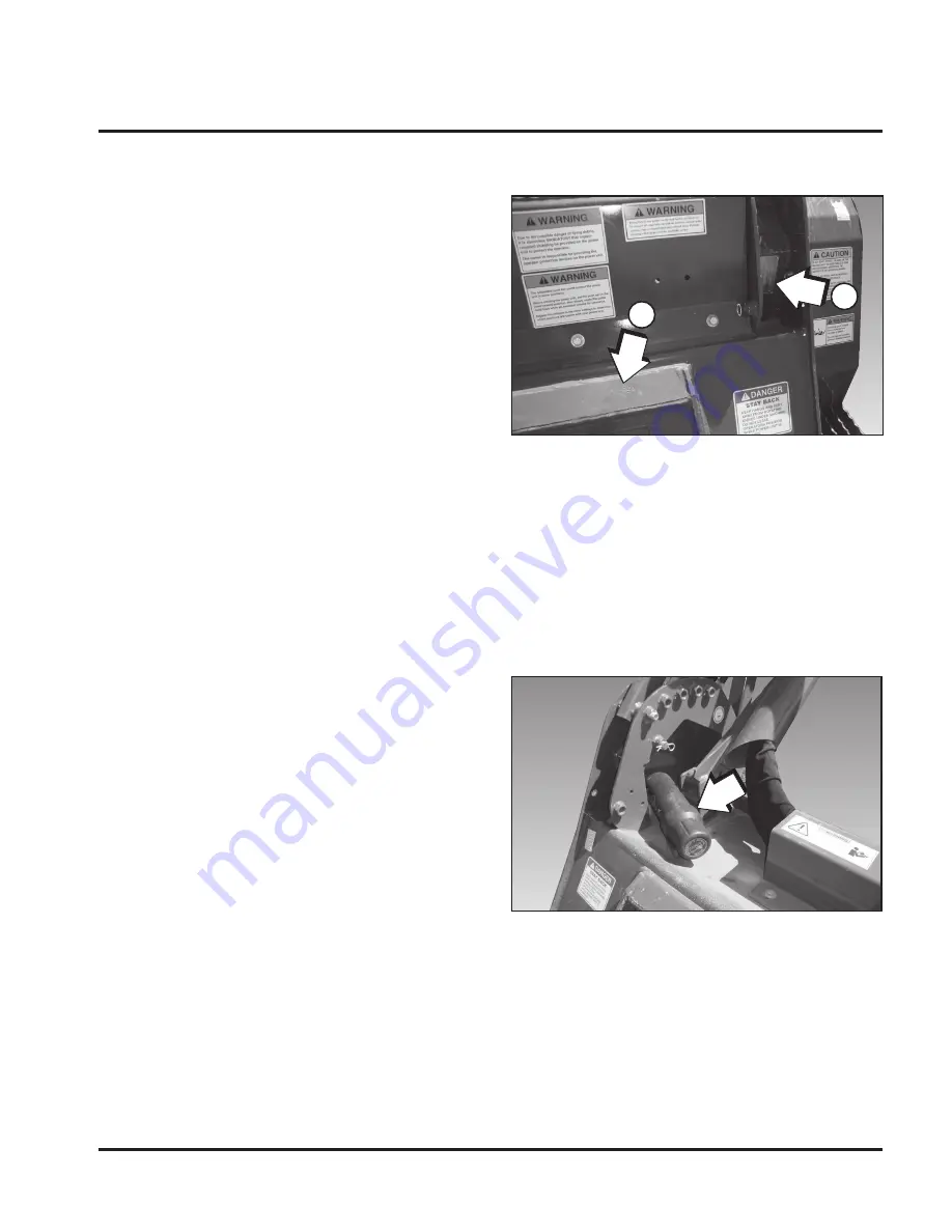
Serial Number Location

NOTE: 

Pusher  bar  arm  has  been  removed  for  picture 
clarity.

The  arrows  above  indicate  the  location  of  the  serial 
number  tag  (1)  and  the  location  of  the  serial  number 
stamped into the frame (2).

Always  use  your  model  and  serial  number  when 
requesting information or when ordering parts.

Manual Storage

Keep the owner’s manual and the entire documentation 
packet  in  the  storage  compartment  provided  on  your 
Carbide  Cutter.  The  owner’s  manual  must  be  available 
for all operators.

Introduction

1

2

Summary of Contents for 51CCH

Page 1: ...Model Number Serial Number Date of Purchase Carbide Cutter 51CCH 61CCH 71CCH Owner s Manual and Parts Book Originating w Serial Number 42 751 N28364 09 26 14...

Page 2: ......

Page 3: ...nd returned to Loftness Specialized Equipment to validate all future warranty claims LIMITATIONS OF WARRANTY LOFTNESS products are designed to provide years of dependable service when proper use and m...

Page 4: ......

Page 5: ...ER PURCHASER Customer Last Name The machine was properly set up adjusted and inspected before delivery The following items were explained to the purchaser How to operate machine properly as shown in t...

Page 6: ......

Page 7: ...ER PURCHASER Customer Last Name The machine was properly set up adjusted and inspected before delivery The following items were explained to the purchaser How to operate machine properly as shown in t...

Page 8: ......

Page 9: ...Procedure 6 Safety Rules 6 Hydraulic Safety 7 Carbide Cutter Identification 8 Safety Decal Locations 9 Set up Instructions Installing the Carbide Cutter to the Loader 13 Checking Rotor Rotation 14 Che...

Page 10: ...embly 933 Open 15 Bar N28472 40 Motor Assembly 1033 Closed 15 Bar N28500 42 Motor Assembly VOAC 60 N20840 44 Overhung Load Adapter N20901 45 Variable Motor Assembly 15 Bar N28205 46 Hydraulic Hose Ass...

Page 11: ...F 8 5 9 75 63 H 8 0 10 3 63 J 9 0 9 75 63 Threshold setting 0 Fixed Displacement 1 2175 PSI Variable Displacement 2 2900 PSI Variable Displacement 3 3400 PSI Variable Displacement Ordering Code Order...

Page 12: ...2 Carbide Cutter OM...

Page 13: ...ner and in accordance with all applicable local state and federal codes regulations and or laws and in compliance with on product labeling and these instructions Make sure that all personnel have read...

Page 14: ...0 2150 RPM 2 3 16 In 56 mm Rotor Bearings Anti Wrap Bearing Protection Heavy Duty Bearing Block Fixed Or Variable Displacement Piston Type Motor Dual Cross Over Relief Protection Pressure Gauge Steel...

Page 15: ...ess for safety decal replacement Loftness cannot anticipate every possible circumstance that may involve a potential hazard The warnings in this owner s manual are not all inclusive Owner s Responsibi...

Page 16: ...nd step plates when getting on and off the machine to prevent falls Keep steps and platform cleared of mud and debris Always have an operator in the machine while the attachment is in operation Never...

Page 17: ...l guards shields and structural members Replace or repair anything that could cause a potential hazard Do not replace components or parts with other than factory recommended service parts To do so may...

Page 18: ...aulic Control Valve Hydraulic Motor Rotor Cutting Teeth Hydraulic Hoses Hydraulic Hose Support Rotor Locking Pin Storage Location Mounting Plate Deflector Chain Support Stand Drive Belt Pressure Gauge...

Page 19: ...diator and oil cooler screens engine compartment and exhaust areas Periodic cleaning will help prevent the possibility of fire The adjustable push bar could contact the power unit in some positions Be...

Page 20: ...SITION WHILE POWER UNIT IS RUNNING DANGER Safety Instructions 8 Part No N28385 WARNING IMPROPER CONNECTION TO THE POWER UNIT S HYDRAULIC SYSTEM COULD CAUSE SERIOUS COMPONENT DAMAGE AND PERSONAL INJURY...

Page 21: ...ERATE OR WORK ON THIS MACHINE UNTIL YOU HAVE CAREFULLY READ AND THOROUGHLY UNDERSTAND THE CONTENTS OF THE OPERATOR S MANUAL NOTE IF YOU DO NOT HAVE AN OPERATOR S MANUAL CONTACT YOUR DEALER OR LOFTNESS...

Page 22: ...12 Carbide Cutter OM...

Page 23: ...late under the top flange 1 on the carbide cutter mounting plate Be careful not to damage the locking levers on the loader mounting plate Tilt the loader mounting plate back until the carbide cutter m...

Page 24: ...the hydraulic output of the loader with a flow meter to see if it corresponds with the factory specifications Checking Rotor Rotation Raise the carbide cutter off the ground and place blocks 1 undern...

Page 25: ...hole from the front as shown Install bushing and bolt 2 and tighten securely against the frame Tighten bolts 3 4 Adjusting the Support Stands Remove the two bolts 1 and support stand 2 Repeat procedur...

Page 26: ...he six nuts 1 and raise or lower the skid to the desired height Re install the six nuts and tighten securely against the skid Rotor Locking Pin Installation Raise the carbide cutter off the ground and...

Page 27: ...sired finished cut appearance will determine proper ground speed Operating Instructions WARNING Due to the potential danger of flying debris it is the owner s responsibility and is ABSOLUTELY MANDATOR...

Page 28: ...ics Raise the loader lift arms and tilt the carbide cutter forward until the push bar extensions are over the log or item being moved Lower the lift arms and position the log between push bar extensio...

Page 29: ...se Proper lubrication is important Too little lubricant will cause premature failure of a bearing Too much lubrication usually causes high operating temperature and early failure of seals Follow all l...

Page 30: ...20 Carbide Cutter OM Lubrication Grease Point Location Belt Tensioner Rotor Bearing right Rotor Bearing left 1 3 2 Maintenance...

Page 31: ...through the opening of the frame bottom grease fitting NOTE Rotor bearings cannot be damaged by over greasing Grease fittings until a small amount of grease is purged from the bearing Interval Daily o...

Page 32: ...t bolt 4 counterclockwise to decrease spring tension when replacing drive belt Remove the belt while belt tension is released NOTE When replacing or installing a new belt align the grooves in the belt...

Page 33: ...pening Install the rotor locking pin See Rotor Locking Pin Installation on page 16 NOTE The Quadco cutter teeth have been heat treated to a specific hardness Care must be taken to avoid overheating th...

Page 34: ...tion WARNING DO NOT allow ANY people or animals within 300 feet of the work area while operating this machine Tooth Sharpening Quadco Option Only Cont d NOTE When re sharpening teeth using a hand grin...

Page 35: ...N28703 Model Code H 42 2017 1513 GPM FIXED DISPLACEMENT MOTOR NUMBER DISPLACEMENT LOFTNESS PART NUMBER ROTOR RPM TOP SHEAVE LOFTNESS NUMBER BOTTOM SHEAVE LOFTNESS NUMBER BELT LENGTH LOFTNESS NUMBER 3...

Page 36: ...ng s Damage to rotor includes bent end of shafts missing balance weights or actual rotor deformity from striking rocks etc Consult factory Uneven Cutting Teeth dull or worn excessively Replace teeth E...

Page 37: ...27 Carbide Cutter OM PARTS IDENTIFICATION Parts Identification...

Page 38: ...utter OM Carbide Cutter Drive Assembly Parts Identification A B C D 1 A Item 10 is not a replacement part 10 9 B 11 12 C D 7 8 23 22 21 CODE J 21 CODE F 21 CODE H 20 19 15 15 18 17 16 15 14 13 2 3 4 5...

Page 39: ...1 N28407 PLATE CARBIDE 71 HOSE SHIELD 12 1 N15974 SHIELD CARB MTR W GAUGE 13 1 N28409 MOTOR ASSY 530 OPEN 1 N28410 MOTOR ASSY 630 CLOSED 1 N28472 MOTOR ASSY 933 OPEN 15 BAR 14 1 N28018 TENSIONER BELT...

Page 40: ...30 Carbide Cutter OM Parts Identification Carbide Cutter Body Assembly 1 2 4 5 6 7 8 9 10 10 14 15 16 6 5 1 17 18 19 11 3 3 6 5 4 12 13 Item 8 is not a replacement part...

Page 41: ...RIGHT 8 Not a replacement part 1 BODY 51 CARBIDE 1 BODY 61 CARBIDE 1 BODY 71 CARBIDE 9 56 N15589 CHAIN CARBIDE REAR 51 66 N15589 CHAIN CARBIDE REAR 61 76 N15589 CHAIN CARBIDE REAR 71 10 2 4375 PIN RO...

Page 42: ...32 Carbide Cutter OM Parts Identification Carbide Cutter Body Assembly Cont d 1 2 3 5 3 2 1 8 15 14 16 17 13 12 11 10 9 6 7 4...

Page 43: ...N20080 ROTOR 71 CARBIDE WITH DOUBLE CUTTERS 5 1 N16445 BUSHING 2 3 16 ID x 2 3 4 OD 6 1 4075 WASHER 2 5 8 OD BEARING RETAINER 7 1 4076 WASHER 1 2 EXT CNTSK LOCK 8 1 N20012 GUARD BEARING WELDED 9 2 401...

Page 44: ...34 Carbide Cutter OM Parts Identification Carbide Cutter Body Assembly Cont d 5 3 2 6 7 3 4 8 3 4 8 12 13 6 14 11 9 10 To belt tensioner 10 To bearing 1 4...

Page 45: ...3 4 FLAT 4 6 4287 WASHER 3 4 LOCK 5 2 4244 BOLT 3 4 x 4 1 2 BOLT GR 5 6 2 N17007 GREASE ZERK 1 8 NPT 7 4 4472 ELBOW 1 8 90 DEG STREET 8 4 4029 BOLT 3 4 x 6 GRADE 5 9 2 4304 10 BULKHEAD FITTING GREASE...

Page 46: ...ly 530 Open N28409 1 2 TO MOTOR COVER PRESSURE GAUGE TO CASE DRAIN 3 4 5 6 7 8 9 10 11 12 13 12 14 Item 3 N21669 parts breakdown 3a 3b 3c 3d Valve Open Loop CW N21669 Schematic Use item 15 in parts li...

Page 47: ...16 x 2 1 4 GRADE 5 6 1 N20976 BLOCK VALVE 7 8 N21914 BOLT SHCS 3 8 x 2 1 2 GRADE 5 8 8 N21916 WASHER HIGH COLLARLOCK 3 8 9 1 N16173 ELBOW 90 DEG 8 MJC 10 MOR 10 1 N20840 MOTOR VOAC 60 11 4 N28502 BOL...

Page 48: ...a 2b 2c 2d Parts Identification Motor Assembly 630 Closed N28410 1 TO MOTOR COVER PRESSURE GAUGE REAR OF MOTOR TO CASE DRAIN 2 4 5 3 6 7 8 9 10 11 12 13 14 13 15 Item 2 N23026 parts breakdown Relief V...

Page 49: ...N21917 WASHER HIGH COLLARLOCK 7 16 5 8 N21915 BOLT SHCS 7 16 x 2 1 4 GRADE 5 6 8 N21914 BOLT SHCS 3 8 x 2 1 2 GRADE 5 7 8 N21916 WASHER HIGH COLLARLOCK 3 8 8 1 N16166 HOSE 3 8 x 24 6 FJIC 8 MOR 9 1 N2...

Page 50: ...23 8 6 9 10 11 12 13 13 12 11 14 15 16 8 MOTOR COVER PRESSURE GAUGE TO ACCUMULATOR 7 TO CASE DRAIN Motor Assembly 933 Open 15 Bar N28472 Item 3 N28203 parts breakdown Relief Valve Open Loop CW N28203...

Page 51: ...10 C I 10 1 N16128 MOUNT ACCUMULATOR W STOPS 11 4 4460 WASHER FLAT 1 4 12 4 4228 WASHER 5 16 LOCK 13 4 4237 NUT 5 16 STANDARD 14 2 4195 BOLT 3 8 x 1 GRADE 5 15 2 4065 WASHER 3 8 LOCK 16 1 N16166 HOSE...

Page 52: ...CD M1 G2 G1 OUT IN Item 3 N28636 parts breakdown Relief Valve Open Loop CW N28636 Schematic MOTOR COVER PRESSURE GAUGE TO CASE DRAIN 1 6 7 9 10 11 12 13 14 15 16 7 17 18 19 20 19 21 22 23 8 MOTOR CAS...

Page 53: ...N16166 HOSE 3 8X24 6FJX 8MOR 8 1 N21992 ELBOW 90 DEG 6 MJIC 10 MOR 9 2 N16125 U BOLT 5 16 X 2 1 2 X 3 1 2 10 1 N16074 ACCUMULATOR 500PSI 10 C I 11 1 N16128 MOUNT ACCUMULATOR W STOPS 12 4 4460 WASHER...

Page 54: ...44 Carbide Cutter OM Motor Assembly VOAC 60 N20840 QTY PART DESCRIPTION 1 N28563 REBUILD SEAL KIT Items with asterisk are included in seal kit 1 1 N28173 SHAFT SEAL 45 X 65 X 7 1 Parts Identification...

Page 55: ...erhung Load Adapter N20901 1 2 3 5 4 6 QTY PART DESCRIPTION 1 N28566 REBUILD KIT Includes Items 1 2 3 4 and 6 1 1 N28447 SEAL FRONT 2 2 N34130 CUP BEARING 3 2 N34131 CONE BEARING 4 1 N28448 SEAL REAR...

Page 56: ...arbide Cutter OM Parts Identification Variable Motor Assembly 15 Bar N28205 QTY PART DESCRIPTION 1 N28560 REBUILD SEAL KIT Items with asterisk are included in seal kit 1 1 N28173 SHAFT SEAL 60 X 80 X...

Page 57: ...N28273 HOSE 1 X 126 HYD W O SLEEVE 16MORB B E 2 2 N28108 ADAPTER 12MOR 16FOR 3 2 N32001 PLUG 1 00 X 3125 4 2 N15893 CAP 3 4 ALUMINUM HOSE 5 1 N15895 CAP 1 2 ALUMINUM HOSE 6 1 N32002 PLUG 3 8 SCH 40 X...

Page 58: ...73 WASHER 5 8 NORDLOCK 3 1 N10508 PULLEY IDLER BELT 4 Varies N28269 WASHER HARDENED 5 8 x 1 3 4 5 1 N28382 SLIDE BELT TIGHT SQ ASSY 6 1 N24211 SPRING BELT TIGHTENER 7 1 4250 NUT STANDARD 1 2 8 1 N2801...

Page 59: ...2 ELBOW 1 4 NPT 90 DEG STREET 4 1 N16335 FLANGE MOUNT 10 5 1 N16331 FLANGE MOUNT GAUGE 8 6 1 N16332 FLANGE MOUNT GAUGE 7 1 N16067 HOSE 1 4 x 24 x 5000 PSI 8 3 N16333 BOLT BHCS 10 32 x 1 9 3 N16133 NUT...

Page 60: ...ARBIDE SPIRAL W O CUTTERS 2 30 N15510 TOOTH DOUBLE CARBIDE 51 36 N15510 TOOTH DOUBLE CARBIDE 61 42 N15510 TOOTH DOUBLE CARBIDE 71 3 60 N17041 WASHER LOCK 5 8 51 72 N17041 WASHER LOCK 5 8 61 84 N17041...

Page 61: ...SPIRAL W O CUTTERS 2 30 N17044 TOOTH CARBIDE DOUBLE PLANER 51 36 N17044 TOOTH CARBIDE DOUBLE PLANER 61 42 N17044 TOOTH CARBIDE DOUBLE PLANER 71 3 60 N17041 WASHER LOCK 5 8 51 72 N17041 WASHER LOCK 5...

Page 62: ...PLANER 71 3 30 N24139 HOLDER TOOTH QUADCO PLANER 51 36 N24139 HOLDER TOOTH QUADCO PLANER 61 42 N24139 HOLDER TOOTH QUADCO PLANER 71 4 60 N17041 WASHER LOCK 5 8 51 72 N17041 WASHER LOCK 5 8 61 84 N170...

Page 63: ...Tooth Assembly Quadco Planer N24281 1 2 3 4 5 3 QTY PART DESCRIPTION 1 1 N24279 TOOTH QUADCO PLANER 2 1 N24139 HOLDER TOOTH QUADCO PLANER 3 2 N17041 WASHER LOCK 5 8 4 1 N26490 SCREW SHCS 5 8 18UNF X...

Page 64: ...8 18UNF STANDARD FINE THREAD 71 3 21 N16473 WASHER 5 8 NORDLOCK 51 24 N16473 WASHER 5 8 NORDLOCK 61 27 N16473 WASHER 5 8 NORDLOCK 71 4 7 N20247 MOUNT CARBIDE REAR CUTTER ANGLE 51 8 N20247 MOUNT CARBID...

Page 65: ...ess in the other settings to determine which positions are usable with your power unit WARNING WARNING Rotor must be stabilized with the rotor locking pin to prevent accidental rotation any time the r...

Page 66: ...TIL YOU HAVE CAREFULLY READ AND THOROUGHLY UNDERSTAND THE CONTENTS OF THE OPERATOR S MANUAL NOTE IF YOU DO NOT HAVE AN OPERATOR S MANUAL CONTACT YOUR DEALER OR LOFTNESS SPECIALIZED EQUIPMENT 650 SOUTH...

Page 67: ...ntification Machine Decals and Signs Cont d Part No 4138 S EAL OF QUALIT Y FEMA F A R M E Q U I P M ENT MANUFACTURERS A S S O C I A T I O N Part No N13517 Part No N26973 Part No N28577 Part No N28505...

Page 68: ...58 Carbide Cutter OM...

Page 69: ...9 10 Hyd Systems Rotor Bearing 2 1875 in Piloted Double Taper Rotor Tip Diameter 17 in 43 2 cm Sheaves Taperlock Belt Four Band 5VX Type Belt Tightener Spring Loaded Tensioner Mount Universal Skid Ty...

Page 70: ...Width B 68 56 in 174 14 cm 78 56 in 199 54 cm 88 56 in 224 94 cm Operating Height C 35 81 in 90 96 cm 35 81 in 90 96 cm 35 81 in 90 96 cm Overall Length D 37 17 in 94 41 cm 37 17 in 94 41 cm 37 17 in...

Page 71: ...ft lb 26 N m 26 ft lb 35 N m 7 16 27 ft lb 37 N m 35 ft lb 47 N m 42 ft lb 57 N m 54 ft lb 73 N m 59 ft lb 80 N m 77 ft lb 104 N m 30 ft lb 41 N m 42 ft lb 57 N m 1 2 42 ft lb 57 N m 54 ft lb 73 N m 6...

Page 72: ...115 in lb 17 N m 150 in lb 6 3 N m 56 in lb M8 14 N m 124 in lb 18 N m 159 in lb 22 N m 195 in lb 28 N m 248 in lb 31 N m 274 in lb 40 N m 354 in lb 15 N m 133 in lb M10 28 N m 21 ft lb 36 N m 27 ft...

Page 73: ......

Page 74: ...www loftness com Loftness Specialized Equipment Inc 650 So Main Street PO Box 337 Hector MN 55342 Tel 320 848 6266 Fax 320 848 6269 Toll Free 1 800 828 7624 Printed in USA Loftness 2014...

Reviews: