background image

95

Grain Bag Unloader OM

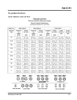
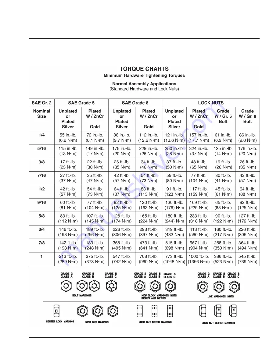
Torque Specifications

Inches Hardware and Lock Nuts

Appendix

Summary of Contents for GrainLogix XLB10

Page 1: ...Model Number Serial Number Date of Purchase Grain Bag Unloader Owner s Manual and Parts Book Originating w Serial Number 51 1532 N22770 Rev M 10 09 19 ...

Page 2: ......

Page 3: ... the LOFTNESS factory or authorized LOFTNESS dealership or in any way so as in LOFTNESS judgment to affect its stability or reliability nor which has been subject to misuse negligence or accident nor to any machine or attachment which shall not have been operated in accordance with LOFTNESS printed instructions or beyond the company recommended machine rated capacity LOFTNESS may elect to have an ...

Page 4: ......

Page 5: ...achine Decals and Signs 10 Set up Instructions Connecting the Grain Bag Unloader 13 Implement Set up Preparing the Hitch 13 Connecting to Truck 14 Installing Grain Bag Unloader to the Tractor 14 Converting Valve to Open Center System 15 Switch to Working Position 16 Knife Sharpening 21 Operating Instructions Getting Started 23 Grain Extraction 26 Pause Operation 28 End of Bag Extraction 28 Bag Rem...

Page 6: ...ag Unloader Base Cont d 64 PTO N153391 66 Grain Bag Unloader Base Cont d 67 6 Bolt Hub 68 GBU Subshields Subassembly 69 GBU Bottom Auger Assembly 70 GBU Bottom Auger Assembly Cont d 72 Hanger Auger N29588 73 GBU Bottom Auger Assembly Cont d 74 Gearbox N22104 75 Driveline N153390 76 GBU Bottom Auger Assembly Cont d 77 Right Extension Auger Assembly 201824 78 10 Left Extension 201807 80 9 Left Exten...

Page 7: ...ness reserves the right to make product improvements to the machine at any time Although great care has been taken to ensure the accuracy of this publication Loftness does not assume any liability for errors or omissions Loftness Specialized Equipment Inc is not responsible for the condition of the grain when it is being stored in or removed from grain bags loaded or unloaded with Loftness built e...

Page 8: ...2 Grain Bag Unloader OM ...

Page 9: ...mbol be alert to the possibility of personal injury and carefully read the message that follows If Safety Decals on this machine are ISO two panel pictorial decals are defined as follows The first panel indicates the nature of the hazard The second panel indicates the appropriate avoidance of the hazard Background color is YELLOW Prohibition symbols such as and STOP if used are RED Be certain all ...

Page 10: ...ine Front Chain Drive Main Drive Shaft Upper Auger Housing Lower Auger Housing Roller Drive Roller Axle Control Valve Jack Hitch Roller Locking Pin Support Arm Storage Compartment Bag Cutting Knife Adjustable Top Deflector Grain Bag Unloader Identification ...

Page 11: ... operator s responsibility to be aware of machine operation and work area hazards at all times Never enter the grain bag Operators are responsible to know the location and function of all guards and shields including but not limited to PTO drivelines gearboxes chain drives augers and are responsible to make certain that all guards are in place when operating the machine Operators are responsible t...

Page 12: ...ion These fluids escaping under high pressure can have sufficient force to penetrate skin and cause serious injury Never check for leaks by using any part of your body to feel for escaping fluid To prevent serious personal injury from escaping high pressure fluid never attempt to inspect service or disassemble any part of the hydraulic system until all pressure has been relieved from the system PT...

Page 13: ...Unloader OM Safety Decal Locations Check and replace any worn torn hard to read or missing safety decals on your machine 1 2 3 4 Part No 4189 1 2 Part No 4256 Part No N23931 3 Part No N23505 4 Safety Instructions 4 ...

Page 14: ...Safety Decal Locations Cont d Part No N22763 Part No N22729 7 8 6 5 6 7 8 9 10 Part No N23506 WARNING SKIN PUNCTURE HAZARD HYDRAULIC LINES Protect hands and body from high pressure fluids N23506 Part No N23504 10 9 Part No 203264 Part No N23507 5 ...

Page 15: ...9 Grain Bag Unloader OM Safety Instructions Safety Decal Locations Cont d Part No N22734 12 12 12 11 11 11 11 Part No N22764 11 ...

Page 16: ... Instructions Section along with their location on the machine See Safety Decal Locations starting on page 7 Check and replace any worn torn hard to read or missing decals on your machine Part No 4136 Part No N28010 Part No 201271 Part No 4132 Part No 4138 Part No N26973 Part No N26971 Part No N26968 Part No N26976 Part No 201844 ...

Page 17: ...11 Grain Bag Unloader OM Safety Instructions Part No N13517 Part No N22759 Part No N13721 Machine Decals and Signs Cont d Part No N24823 Part No N24822 Part No N33102 Part No N33108 ...

Page 18: ...12 Grain Bag Unloader OM ...

Page 19: ...ch with the drawbar hammer strap could result in machine damage and or the machine could separate from the tractor if the clevis pin fails serious injury and or death may result WARNING Never use a hitch without a clevis on a straight drawbar Using a hitch without a clevis on a straight drawbar could result in machine separating from tow vehicle and or damage to the machine serious injury and or d...

Page 20: ...osses is 53 5 inches 136 cm If the distance is more or less than that refer to the PTO driveline manufacturer s literature for procedures for adjusting the length It may also be possible to move the draw bar location on the tractor Procedure continued on following page Connecting the Grain Bag Unloader Cont d 1 3 2 4 Back the tractor up to the hitch of the unloader Insert pin 1 1 1 8 in to 1 1 4 i...

Page 21: ... Liters per min Install the 7 pin electrical harness to the tractor s electrical connector NOTE If your tractor is not equipped with a 7 Pin electrical connector an adapter or special wiring may be needed Secure the electrical harness and all hydraulic hoses up and away from the PTO driveline area Converting Valve to Open Center System The control valve is shipped to accommodate closed center hydr...

Page 22: ...afe place should the need arise to convert back to a closed center hydraulic system Reinsert the fitting and reconnect the swivel coupler Tighten all Start the tractor and engage the hydraulic system 1 Test the unloader hydraulic system by raising the unloader with the axle lever Move the axle lever 1 up to raise the unloader NOTE If the unloader is not operating correctly the hydraulic hoses may ...

Page 23: ...he right cross auger guards extensions and the left extension brace from the stored position 1 6 5 3 4 2 Install the cross auger extension 1 onto the center auger shaft 2 Install the extension auger cage 3 to the main unit 4 using four bolts 5 and nuts 6 Do not tighten at this time do the next step first 1 1 Align the holes of the auger extension with the holes of the center auger shaft Secure wit...

Page 24: ...TE Do not use a cross bolt in this location 1 Install the cross auger drive shaft guard 1 and secure with the eight 3 8 bolts provided See Torque Specifications on page 95 Remove the left cross auger guard and extension from the stored position 1 2 Install the left cross auger extension 1 onto the center auger shaft 2 1 2 3 4 Install the left extension auger cage 1 to the main unit 2 using four bo...

Page 25: ...in the previous step See Torque Specifications on page 95 1 1 Install the left extension brace 1 using the 1 2 bolts and nuts provided Set up Instructions 2 1 Remove the support arm lower pin 1 and retaining clip 2 on the left side of the unloader 1 Swing support arm up and insert pin 1 into temporary mounting position 1 Pull out the spring loaded locking pin 1 to release the roller Procedure cont...

Page 26: ...asses ear protection respirators gloves hard hats safety shoes and other protective clothing when required 1 2 Remove the lower retaining clip 1 and pin 2 on the bag cutting knife CAUTION The Bag Cutting Knife is SHARP Use extreme care when placing the bag cutting knife in the work or transport position Use of gloves is recommended 2 1 Using the handle pivot bag cutting knife to the operating posi...

Page 27: ...emery cloth slowly up and down the knife edge using light pressure to remove the paint Periodically check the sharpness of the bag cutting knife Repeat this procedure to maintain a sharp edge throughout the life of the machine Engage the hydraulics on the tractor WARNING Always have an operator in the tractor while the machine is in operation 1 2 Raise the top auger 1 to the operating position Mov...

Page 28: ...22 Grain Bag Unloader OM ...

Page 29: ... bag Center the tractor and unloader on the grain bag NOTE Proper centering in the beginning will make the grain extraction process much easier NOTE If the unloader is off center during set up or becomes off center during operation the grain bag will roll up unevenly on the bag roller and put undo stress on the unloader If this occurs stop operation roll out bag re align the tractor and unloader a...

Page 30: ...e or the bag could keep opening completely from being stretched and full of grain Do not cut into the tension portion of the bag Second make a vertical cut just below the horizontal cut all the way to the end of the bag The cut should line up with the unloader s cutting knife 1 NOTE If there is not enough grain bag to attach it to the unloader s roller some grain will need to be extracted manually...

Page 31: ...before bag is attached and in operational position The bag could get entangled in the cross augers Wrap the grain bag over the top side of the roller 1 Wrap the bag evenly and completely around the roller to secure the bag on the roller teeth 1 NOTE It is very important that the bag be wrapped around the roller as evenly as possible Make sure the bag engages the roller teeth 1 Move the axle lever ...

Page 32: ... line with the starting cut on the grain bag A NOTE It may be necessary to use a wooden push pole to reach over the bag and help align the plastic bag with the starting cut and the cutter A Grain Extraction 1 Move the auger lever 1 up to raise the top auger into the operating position NOTE Once the grain bag has been opened it is recommended that the grain bag be emptied completely 1 Move the grai...

Page 33: ... the roller speed 1 and roller height 2 to avoid grain build up by the roller and the lower mound at the bottom of the bag Operating Instructions The grain should just cover the cross augers Cross auger height should be 3 to 4 76 102 mm above the ground The mound at the bottom of the bag should be adequate distance from the tires on the grain bag unloader Procedure continued on following page ...

Page 34: ...to stop bag roller rotation Gradually decrease the PTO speed and disengage the tractor PTO To restart operation see Grain Extraction on page 26 End of Bag Extraction NOTE Once the grain bag is opened it is recommended that the grain bag be emptied completely It is important to reach the end of the grain bag with the unloader as centered as possible Grain can be extracted until the cross augers tou...

Page 35: ...s 1 to disengage the roller clutch 2 until it locks in the open position The roller should move freely NOTE The cogs should rest on the inner cogs Drive the tractor forward slowly until the bag is fully unrolled Watch and guide the bag as it is coming off the roller NOTE Remaining grain will need to be cleaned up with a loader or grain vac Fold or roll the used bag as small as possible NOTE The gr...

Page 36: ...d to the center on both sides Place one plank 1 underneath the grain bag approximately 12 in 304 8 mm back from the end of the bag Place a second plank 2 on top of the grain bag 3 and first plank Align the top and bottom planks and fasten the two planks together Roll the grain bag around the planks a minimum of two times Position the planks approximately 3 ft 914 m back underneath the grain bag NO...

Page 37: ... position Insert pin 1 and retaining clip 2 to secure bag cutting knife CAUTION The Bag Cutting Knife is SHARP Use extreme care when placing the bag cutting knife in the work or transport position Use of gloves is recommended Engage the hydraulics on the tractor 1 2 Lower the top auger 1 to the transport position Move the auger lever 2 down to lower the top auger 2 1 Remove support arm pin 1 and r...

Page 38: ... transport position 1 The roller will lock into place with the spring loaded locking pin 1 1 Remove pin 1 and lower the support arm into its original position 2 1 Reinsert the support arm lower pin 1 and retaining clip 2 on the left side of the unloader 1 Move the axle lever 1 up to raise the unloader Procedure continued on following page Operating Instructions ...

Page 39: ...ing or disconnecting a PTO shaft Place the PTO driveline in the stored position NOTE Disconnecting the PTO driveline is not required when transporting the grain bag unloader with a tractor 2 1 Remove the chain 1 and rotate the PTO driveline up into the stored position Reinstall the retaining pin 2 NOTE The electrical connector must stay attached for transporting on the highway with a tractor See I...

Page 40: ...rea for road travel 1 Remove the cross auger drive shaft guard 1 2 1 2 1 Loosen jam nuts 1 then loosen set screws 2 1 2 Remove the right cross auger extension 1 from the center auger 2 Install the cross auger guard auger extension and the left extension brace removed in the next step in the stored position using the same hardware 1 1 Remove the left extension brace 1 Procedure continued on followi...

Page 41: ...Bag Unloader OM Switching to Transport Position Cont d 1 2 Remove left cross auger extension 1 from center auger 2 Install the left cross auger guard and extension into the stored position Operating Instructions ...

Page 42: ...36 Grain Bag Unloader OM ...

Page 43: ...and rear X 39 Frame Drive Shaft Front Bearings X 39 Main Drive Shaft X 39 Bag Roller Bearing X 39 Auger Hinge Hanger Bearing X 39 Main Drive Shaft At Rear X 40 PTO Cross And Bearing X 40 Overhung Load Adapter X 41 Cross Auger Bearing X 41 Cross Auger Left End Bearing X 41 Maintenance HOURS SERVICE POINTS SERVICE REQUIRED P A G E C H E C K G R E A S E L U B R I C A T E C H A N G E A D J U S T Every...

Page 44: ...80W 90 gear lube 90 Gearbox 24 oz 50 Gearbox 24 oz 3 Storing Lubricants Your machine can operate at top efficiency only if clean lubricants are used Use clean containers to handle all lubricants Store them in an area protected from dust moisture and other contaminants Lubrication Grease Points Use an SAE multipurpose high temperature grease with extreme pressure EP rating Also acceptable is an SAE...

Page 45: ...Drive Shaft Front Bearings 1 Interval Every 8 hours of operation 1 Location Main Drive Shaft 1 two locations Interval Every 8 hours of operation Maintenance 1 Location Bag Roller Bearing 1 both ends Interval Every 8 hours of operation 1 Location Auger Hinge Hanger Bearing 1 Interval Every 8 hours of operation 1 Location Auger Hinge 1 Interval Every 40 hours of operation ...

Page 46: ... the axle Interval Every 40 hours of operation 1 1 Location Lower Roller Pivot Points 1 Interval Every 40 hours of operation 1 1 Location Roller Pivot Points 1 Located where the roller and the main frame pivots Interval Every 40 hours of operation 1 Location PTO Cross and Bearing 1 Located in the rear cross auger and chain drive housing in the top compartment Interval Every 8 hours of operation ...

Page 47: ...ung Load Adapter 1 Interval Every 8 hours of operation Center Auger Chain Coupler 2 PTO Cross and Bearing 3 Interval Every 40 hours of operation 1 Location Cross Auger Left End Bearing 1 Interval Every 8 hours of operation 2 2 1 1 Location Cross Auger U Joints 1 Cross Auger Bearings 2 Interval Every 8 hours of operation 1 Location Lower Discharge Auger Bearing 1 Interval Every 8 hours of operation...

Page 48: ...tion Cross Auger Driveline U Joint 1 Inner Outer Bearing 2 Interval Every 8 hours of operation 1 2 2 Location Cross Auger Right End Right Auger Extension Chain Housing 1 Interval Every 40 hours of operation Inner Outer Bearing 2 Interval Every 8 hours of operation Location Wheel Hub Bearings Interval Yearly Location Front Chain Housing Interval Every 40 hours of operation ...

Page 49: ...Lube Remove the oil level plug 1 and fill plug 2 Add 80W 90 gear lube through the fill hole until it flows out the oil level hole Install oil level plug 1 and fill plug 2 Draining Gear Lube Place a drain pan underneath the drain plug of the gearbox Remove the drain plug 3 and fill plug 2 Drain the gear lube until the pan is empty Reinstall the drain plug Remove the oil level plug 1 add 3 Qts of 80...

Page 50: ...g Oil Level Of 90 Gearbox 1 2 2 Remove cap 1 and breather 2 to check oil level The oil level should be approximately 1 inch below the breather opening Location Top of Lower Unit Left side Interval Annually NOTE The gearbox holds 24 oz 80W 90 gear lube Checking Oil Level of Bag Roller Gearbox 1 2 in Remove plug 1 and check oil level The oil level should be approximately 2 inches below the plug open...

Page 51: ...s until the deflection is approximately 1 2 in 12 7 mm NOTE Do not over tighten the chains Overtightening the chains will put undue stress on the chains and other components of the roller drive Roller Drive Chain Adjustment WARNING Never attempt to make any adjustments while the tractor engine is running or the key is in the ON position in the tractor Before leaving the operator s position disenga...

Page 52: ... Adjust the Tractor Unloader GBU Grain bag not started correctly Adjust grain bag Grain building up by the roller Roller wind is set too fast Decrease roll up speed Cross augers set too high Lower cross augers Bag cutting knife not cutting correctly Bag coming off knife Switch to lower knife setting Cutting knife is not locked in the operation position Install pin and clip to lock the cutting knif...

Page 53: ...47 Grain Bag Unloader OM PARTS IDENTIFICATION Parts Identification ...

Page 54: ...48 Grain Bag Unloader OM This page intentionally left blank Parts Identification ...

Page 55: ...4 1 7189 04 KEY 5 16 X 1 3 4 5 2 N37789 KIT GBU10 CROSS AUG BOLT 6 4 4054 NUT LOCK 1 2 7 8 4068 WASHER 1 2 SAE FLAT 8 4 4467 BOLT 1 2 x 3 1 4 GRADE 5 NOTE Item 5 Cross Auger Bolt Kit is shipped in the toolbox Use part number N37789 to order a complete bolt kit items 6 9 For parts breakdown of item 2 see page 80 for 201807 and page 81 for 202182 For parts breakdown of item 3 201824 see page 78 3 2 ...

Page 56: ...1 2 X 1 1 2 GRADE 5 5 2 N22210 SCREW 3 8 16 X 3 4 SCKT HD SET 6 1 7121 03 KEY 3 8 X 2 7 4 4233 NUT STANDARD 3 8 8 4 4065 WASHER 3 8 LOCK 4 23 24 25 26 25 40 40 27 28 28 27 25 26 25 24 23 29 3 18 17 30 20 35 3 4 31 32 33 34 36 37 38 39 41 41 41 3 18 22 3 21 20 4 3 19 18 17 16 15 14 3 13 12 11 4 10 9 8 7 1 3 4 5 2 6 5 For parts breakdown of item 1 N22193 see page 52 For parts breakdown of item 2 N22...

Page 57: ...E FRONT BEARING 22 4 4012 BOLT 1 2 X 1 1 4 GRADE 5 23 2 4288 NUT 3 4 STANDARD 24 2 4287 WASHER 3 4 LOCK 25 4 4505 WASHER 3 4ID X 1 1 4OD X 10GA 26 2 8230 SPROCKET IDLER G1 80 CHAIN 27 2 4071 WASHER 3 4 FLAT 28 2 4028 BOLT 3 4 X 2 3 4 GRADE 5 29 4 4015 BOLT 1 2 X 2 GRADE 5 30 1 N33269 SHAFT GBU FRONT DRIVE LOCKED 31 1 N22070 PIN GBU ROLLER TRANSPORT LOCK 32 1 N22286 PIN ROLL 1 4 X 2 1 2 33 1 N22253...

Page 58: ...B SHAFT GEAR 1 1 6T 4 1 N26560 SUBA CROSS SHAFT GEAR R50 6T 5 4 N26549 BRG CONE TK 14137A 1 375 6 4 N26548 BRG CUP TK 14276 2 717 7 1 N26561 RETAINING RING EXT 1 375 SHFT 8 2 N26550 SEAL 1 375 2 00 0 313 R TC 9 3 N26554 PLUG 1 2 14NPT SCHD W 3M 10 9 N26562 BOLT 3 8 16 x 1 50 SHCS 11 1 N26555 PLUG 1 8 27 NPT TO VENT 5 PSI 12 1 N26556 BUSHING 1 2 NPT TO 1 8 NPT 13 1 N26551 SEAL END CAP 2 00 0 31 ...

Page 59: ...loader OM 4 3 2 1 QTY PART DESCRIPTION 1 1 N26557 HSG R500 MACH TAP STD 2 1 N26558 HSG MACH THRU R500 3 1 N26559 SUBA STUB SHAFT GEAR 1 1 6T 4 1 N26560 SUBA CROSS SHAFT GEAR R50 6T U Joint N22204 Parts Identification ...

Page 60: ... GRADE 5 2 12 4155 WASHER LOCK 1 2 3 1 N22409 PIN ROLLER PIVOT SHAFT 4 11 4013 BOLT 1 2 X 1 1 2 GRADE 5 5 1 N22400 ROLLER GBU 10 ASSEMBLY 6 11 4250 NUT STANDARD 1 2 7 1 N41036 UNIT GBU10 COMP LOWER 2 1 2 3 5 4 2 7 6 For parts breakdown of item 5 N22400 see page 86 For parts breakdown of item 7 see pages 70 72 74 and 77 ...

Page 61: ...01275 COVER GBU10 FRONT CHAIN BOT 7 1 N24248 CHAIN SAFETY W MOUNT HARDWARE 8 5 4004 BOLT 5 16 X 3 GR 5 9 5 N21365 CLAMP 3 8 DOUBLE HOSE 10 5 N13383 CLAMP DBL 1 2 SUPP HOSE QTY PART DESCRIPTION 1 1 202592 GASKET 3 00 X 14 63 X 25 2 1 N41124 WELDMENT GBU10 SADDLE 3 2 4979 NUT LOCK 3 8 SER FLG 4 1 N41127 U BOLT 3 8 16 X 4 X 6 5 8 SQ 5 1 N33029 AUGER GBU10 TOP W ADJ DEF 6 1 N22785 PIN GBU HINGE FIXED ...

Page 62: ...14 13 11 Detail D Detail E Detail E Detail A Detail F Detail F Detail D Detail C Detail C Detail A Detail B Detail B Parts Identification Grain Bag Unloader Base For parts breakdown of item 1 200623 see page 58 Bolts item 10 N28436 are used when clamps are double stacked ...

Page 63: ... 6 X 1 GRADE 5 5 2 4241 BOLT 5 6 X 1 1 2 GRADE 5 6 1 N19768 STOP CYLINDER 9 5 SAFETY 7 1 4093 PIN 3 8 X 3 2 75 USEABLE 8 1 4089 CLIP HAIRPIN 093 X 1 5 8 9 8 N21365 CLAMP 3 8 DOUBLE HOSE 10 3 N28436 BOLT 5 16 X 2 1 4 GR5 11 2 200624 VALVE CHECK DUAL PILOT INLINE 12 4 4002 BOLT 1 4 X 2 1 4 GRADE 5 13 4 3183 WASHER FLAT 1 4 14 2 4050 NUT 1 4 LOCK Parts Identification ...

Page 64: ...TION 1 1 202570 VALVE PORT RELIEF 50 90 BAR 2 1 202571 VALVE PORT RELIEF 91 130 BAR 3 1 202572 CARTRIDGE ADJUSTABLE FLOW Parts Identification Auger to Valve Port V2 1 3 2 Auger to Valve Port V1 Tank Motor Motor Axle to Valve Port V2 Axle to Valve Port V1 Pressure ...

Page 65: ...ON 1 1 N37632 MOTOR EATON 3 6 CID N39036 KIT HYD MOTOR N37632 SEAL 2 2 N22720 ELBOW 45 DEG 6MJIC 10MOR 3 2 N22725 HOSE 3 8 X 140 6FJX 6FJX 45 4 2 N17022 ADAPTER 6MJIC 8MOR 5 1 200623 VALVE 3 SPOOL For parts breakdown of item 5 200623 see page 58 NOTE Items 2 3 and 4 are included in the complete hydraulic hose kit 201842 Parts Identification ...

Page 66: ...NLINE 6 4 N20037 ELBOW 90 DEG 6MJIC 8MOR 7 2 201848 HOSE 3 8 X 19 6FJX 6FJX 8 1 N21715 CYLINDER 3 X 8 HYD 3000 PSI 1 N26540 KIT SEAL 2 4 3 5 Port V2 Port V1 6 7 7 8 6 3 4 1 2 Axle connection to Valve Port V2 on Check Valve item 5 Axle connection to Valve Port V1 on Check Valve item 5 Port C2 Port C1 NOTE Items 2 3 4 6 and 7 are included in the complete hydraulic hose kit 201842 For parts breakdown...

Page 67: ...6MJIC 8MOR 6 1 200624 VALVE CHECK DUAL PILOT INLINE 7 2 201850 HOSE 3 8 X 30 6FJX 6FJX 45 8 2 N22722 RESTRICTOR 6MJIC 8MOR 031 9 1 200623 VALVE 3 SPOOL NOTE Items 2 3 4 5 7 and 8 are included in the complete hydraulic hose kit 201842 For parts breakdown of item 9 200623 see page 58 2 1 2 3 5 5 7 8 9 8 7 5 6 5 4 Auger connection to Valve Port V2 on Check Valve item 6 Auger connection to Valve Port ...

Page 68: ... Detail A 5 4 1 2 Tank 3 Pressure 9 11 10 13 12 5 5 12 13 6 8 5 7 8 Hydraulics Tractor and Diverter Connections NOTE Items 1 3 5 10 and 12 13 are included in the complete hydraulic hose kit 201842 For parts breakdown of item 4 200623 see page 58 Parts Identification ...

Page 69: ...01405 ADAPTER 12MJIC 8MOR 4 1 200623 VALVE 3 SPOOL 5 4 N11825 COUPLER 1 2 MALE PIONEER 6 1 N24823 DECAL TANK 7 1 N24822 DECAL PRESSURE 8 2 N22719 HOSE 1 2 X 264 8MP 12FJX 9 1 N29846 RESTRICTOR 6MJIC 6MOR 031 10 1 N24821 ADAPTER 6MOR 6MJIC 11 1 N30999 CYLINDER 1 X 4 HYD 10 COMP 12 2 N23833 ADAPTER 6MJIC 8MP 13 2 N29845 HOSE 1 4 X 500 6FJX 6FJX Parts Identification ...

Page 70: ...ader Base Cont d For parts breakdown of item 9 N153391 see page 66 NOTE Place these components in the toolbox Item 15 N37609 Hitch conversion kit Item 18 201013 PTO shear bolts and nuts 1 2 3 2 4 5 6 7 8 15 16 17 18 14 13 12 11 6 10 9 24 25 26 27 23 22 19 20 21 ...

Page 71: ... 11 1 7121 03 KEY 3 8 X 2 12 1 4061 NUT 3 8 JAM 13 1 4082 SCREW SQ HEAD SET 3 8 X 1 1 4 14 1 8047 JACK BULLDOG SWL 158DTSF 15 1 N37609 KIT GBU HITCH CONV PART 16 2 4486 WASHER 1 2 FLAT 17 2 4012 BOLT 1 2 X 1 1 4 GRADE 5 18 1 201013 GROUP GBL XLB PTO SHEAR BOLT 19 1 N25105 TOOLBOX WINCH STORAGE 20 1 N16290 LIGHT RIGHT 21 1 N16289 LIGHT LEFT 22 8 N105230 NUT LOCK 1 4 SER FLANGE 23 8 4000 BOLT 1 4 X ...

Page 72: ...tification PTO N153391 QTY PART DESCRIPTION 1 1 N153457 JOINT SHAFT HALF GUARDED 2 1 N153458 JOINT TUBE HALF GUARDED 3 1 N153459 BALL SHEAR 35 4 2 N153460 CROSS KIT 35R 5 1 N153461 OUTER GUARD 6 1 N153462 INNER GUARD 7 1 8209 08 YOKE 35 ...

Page 73: ...4 NUT LOCK 1 2 TOP 2 2 4467 BOLT 1 2 x 3 1 4 GRADE 5 3 2 N25199 SPINDLE GBL 4 2 N23778 HUB 6 BOLT 6 PAT W STUDS QTY PART DESCRIPTION 1 1 N33066 CHAIN GBU10 HEIGHT GAUGE 2 1 N10177 LINK 3 8 CHAIN CONNECTOR 3 2 201834 TIRE MNTED 12 5L 15SL 10 PLY For parts breakdown of item 4 N23778 see page 68 4 3 2 1 1 2 3 ...

Page 74: ...WASHER 6 BOLT HUB 5 1 8082 08 NUT CASTLE P251701 SPINDLE 6 1 8082 09 PIN COTTER 6 BOLT HUB 7 1 8082 10 CAP END 6 BOLT HUB 8 NA NA HUB 6 BOLT STUD N23778 SERVC 9 6 N23764 NUT LUG 9 16 18UNF N23778 10 1 8082 02 CUP BEARING LARGE 6BLT HUB LM501310 11 1 8082 05 CUP BEARING SMALL 6BLT HUB LM67010 12 NA NA CASTING HUB 6 BOLT NO PARTS 13 6 N27304 STUD HUB 9 16 18UNF 14 1 N23778 HUB 6 BOLT 6 PAT W STUDS 6...

Page 75: ...R GBU10 LOWER UNIT 1 5 2 N22346 WASHER 1 38ID X 2 13OD X 14GA 6 2 N22192 PIN LINCH 3 16 X 1 9 16 7 1 N37607 BRACE GBU10 FLIP UP FRAME 8 2 N22343 PIN 5 8 X 3 BENT HITCH 9 1 4329 PIN COTTER 7 32 X 2 1 2 10 6 N37128 KNOB 5 16 X 1 11 3 N33672 COVER GBU10 FRAME SWINGING 12 6 N33677 NUT RIVOT 5 16 FOR 3 16 MAT GBU Subshields Subassembly 3 2 1 4 5 6 7 6 8 8 5 9 10 10 10 11 11 11 12 12 12 ...

Page 76: ...70 Grain Bag Unloader OM Parts Identification GBU Bottom Auger Assembly 24 23 22 21 20 19 16 17 18 23 25 25 25 27 26 1 2 3 3 9 8 4 3 5 6 7 15 14 10 11 12 11 11 13 ...

Page 77: ...PT DRAIN FILL PLUG 12 1 N22268 PAN GBU OIL 13 12 4573 BOLT 1 4 x 3 4 SER FLANGE 14 4 4231 WASHER LOCK 1 4 15 4 4001 BOLT 1 4 x 1 3 4 GRADE 5 16 1 N30965 CHAIN GBU10 MAIN AUG 80 ROLLER 42 P 17 1 N29997 LINK 80 CHAIN HALF UST 18 1 N29998 LINK 80 CHAIN CONNECTOR UST 19 1 4468 SCREW 1 2 20UNF x 1 1 4 FN TD FL HD CAP 20 1 4076 WASHER 1 2 EXT CNTSK LOCK 21 1 4075 WASHER 2 5 8 OD BEARING RETAINING 22 1 N...

Page 78: ...K 5 8 TOP 5 1 N29588 HANGER GBU12 AUGER 6 2 4021 BOLT 5 8 X 1 3 4 GRADE 5 7 1 N22677 AUGER GBU BOTTOM W COMPONENTS 8 4 4006 BOLT 3 8 X 1 1 2 GRADE 5 9 1 N25470 GREASE ZERK 1 4 SCREW IN LONG 10 1 N37161 OHLA GBU SPLINED RADIUS 11 4 4052 NUT LOCK 3 8 12 1 4105 GREASE ZERK 1 4 SCREW IN For parts breakdown of item 5 N29588 see page 73 4 2 4 2 3 2 1 2 1 5 4 2 2 6 7 8 9 10 11 12 Parts Identification ...

Page 79: ...ART DESCRIPTION 1 2 4024 BOLT 5 8 x 2 3 4 GRADE 5 2 2 4055 NUT LOCK 5 8 TOP 3 4 4069 WASHER FLAT 5 8 4 1 N30239 BEARING 2 7 16 PLW BLK 2 BOLT 5 1 N29589 BRACKET GBU12 AUGER HANGER 6 3 N29593 SHIM GBU12 AUG HANGER BRK 1 6 4 3 2 5 3 Parts Identification ...

Page 80: ... CHAIN 60 DOUBLE 20 PITCH 7 1 N25115 SPROCKET 6020 F 1 1 2 RB 8 1 7121 03 KEY 3 8 X 2 9 4 4006 BOLT 3 8 X 1 1 2 GRADE 5 10 1 N37201 OHLA GBU10 1 1 2 KEYED 11 4 4052 NUT LOCK 3 8 12 1 N25403 ELBOW 45 DEG 1 4 28UNF 1 8FP 13 1 4304 HOSE GREASE 1 8 X 15 14 1 N25125 ELBOW 90 DEG 4FJIC 4MJIC 15 1 4304 10 BULKHEAD FITTING GREASE HOSE 16 1 N17007 GREASEZERK 1 8 NPT 1 2 16 15 14 13 12 11 10 9 8 7 6 5 4 3 F...

Page 81: ...6 SUBA SHAFT GEAR H130 4 1 N26547 SUBA SHAFT GEAR H130 5 4 N26548 BRG CUP TK 14276 2 717 6 4 N26549 BRG CONE TK 14137A 1 375 7 3 N26550 SEAL 1 375 2 00 0 313 R TC 8 1 N26551 SEAL END CAP 2 00 0 312 9 7 N26552 BOLT 3 8 16 X 2 25 SHCS 10 2 N26553 PLUG 1 4 18 NPT SCHD W 3M 11 2 N26554 PLUG 1 2 14 NPT SCHD W 3M 12 1 N26555 PLUG 1 8 27 NPT VENT 5 PSI 13 1 N26556 BUSHING 1 2 NPT TO 1 8 NPT ...

Page 82: ... Bag Unloader OM Parts Identification Driveline N153390 QTY PART DESCRIPTION 1 1 N153454 JOINT AND SHAFT HALF 2 1 N153455 JOINT AND TUBE HALF 3 2 N153456 YOKE 35 SLIDE LOCK 4 2 N35479 CROSS KIT 35E 1 3 2 4 4 3 ...

Page 83: ...SHER 1 2 SAE FLAT 5 2 N30230 BEARING 1 1 2 DODGE 2BLT FLG 6 4 4054 NUT LOCK 1 2 TOP 7 2 N37621 SHAFT GBU10 CTR UJT AUG WSL 8 4 7121 03 KEY 3 8 X 2 9 4 4061 NUT 3 8 JAM 10 4 N26799 SCREW SET 3 8 X 3 4 SQ HD 11 2 N37614 U JOINT 1 1 2 KYD 1 1 2 KYD 12 2 4052 NUT LOCK 3 8 13 2 4978 BOLT 3 8 X 3 1 4 GRADE 5 14 1 N37622 DRIVE GBU10 EDLU CRS AUG CTR 1 2 2 1 3 4 5 4 6 7 8 9 10 11 12 8 14 10 13 9 10 10 9 8...

Page 84: ...5 SPROCKET 6020 F 1 1 2 RB 5 1 N25117 CHAIN 60 DOUBLE 20 PITCH 6 5 N29075 NUT LOCK 1 2 SERRATED FLANGE 7 4 N18360 BOLT 1 2 13 X 1 1 4 SER FLG 8 1 201825 CAGE GBU10 DRV EXT 9 12 202579 BOLT 1 2 X 1 1 2 SER FLG 10 2 N30229 BEARING 1 1 2 DODGE 4 BLT FLG 6 40 1 2 3 4 5 4 3 6 7 8 9 10 11 12 13 14 15 16 17 18 19 10 9 20 21 9 19 17 16 22 24 25 26 27 28 29 28 30 31 32 33 11 9 21 20 23 34 35 36 35 37 35 36...

Page 85: ...NG 1 1 2 DODGE 2BLT FLG 22 1 201832 SHAFT GBU10 TOP DRIVE 23 1 7121 07 KEY 3 8 X 2 1 2 24 12 N26743 BOLT 3 8 X 1 SER FLG 25 1 201273 COVER GBU ED LU CHAIN BOX 26 1 4288 NUT 3 4 STANDARD 27 1 4287 WASHER 3 4 LOCK 28 2 4505 WASHER 3 4ID X 1 1 4OD X 10GA 29 1 N22765 SPROCKET IDLER 80B10 30 3 4479 WASHER 2OD X 3 4ID X 1 4TK 31 1 N148409 PLATE GBU10 EDLU DRV CHN BOX 32 1 4071 WASHER 3 4 FLAT 33 1 4297 ...

Page 86: ...UGER GBU10 ED LEFT CROSS 2 2 N30387 BOLT 1 2 X 2 1 4 GRADE 5 3 2 4068 WASHER 1 2 SAE FLAT 4 1 N30230 BEARING 1 1 2 DODGE 2BLT FLG 5 8 N29075 NUT LOCK 1 2 SERRATED FLANGE 6 6 N18360 BOLT 1 2 13 X 1 1 4 SER FLG 7 1 201808 HOUSING GBU LEFT EXT 8 1 201811 BRACKET GBU10 LEFT EXT BTM 1 7 5 6 4 3 2 1 5 8 5 6 6 5 ...

Page 87: ...1 1 2 DODGE 2 BLT FLG 7 2 4013 BOLT 1 2 x 1 1 2 GRADE 5 8 1 N33683 AUGER GBU09 ED LU LEFT PUR 9 2 4467 BOLT 1 2 x 3 1 4 GRADE 5 10 2 N30387 BOLT 1 2 x 2 1 4 GRADE 5 11 6 N29075 NUT LOCK 1 2 SERATED FLANGE 12 1 202191 BRACKET GBU9 LEFT EXT BRC 13 4 N18360 BOLT 1 2 x 1 1 4 SERATED FLANGE 14 1 202194 ANGLE GBU9 LEFT EXT BRACE 9 5 4 5 5 4 5 9 8 7 1 2 5 6 5 4 3 11 11 13 13 14 11 13 11 13 12 11 11 5 10 ...

Page 88: ...82 Grain Bag Unloader OM Parts Identification GBU Roller Drive and Drive Shield 23 5 6 7 8 9 10 11 12 13 14 15 16 17 18 19 20 21 22 4 1 25 27 26 28 26 29 27 2 2 3 9 24 ...

Page 89: ... BOLT 3 8 x 3 GR 5 FULL THRD 13 1 N30257 SPACER GBU10 ROLLER SPROCKET 14 1 N22505 SPROCKET GBU ROLLER DRIVE CLUTCH 15 1 N22202 CHAIN 60 ROLLER 92 25 LONG 16 1 N21695 WASHER 3 OD x 2 1 32 ID 18 GA 17 1 N22510 DRIVE GBU ROLLER INNER 18 1 N22529 CONNECTOR GBU CLUTCH 19 1 N22531 GUIDE GBU SPRING CLUTCH SPRING 20 1 N22253 SPRING COMPRESSION LHC 148U 03S LEE SPRING 21 1 N22532 WASHER GBU SPRING CLUTCH S...

Page 90: ...3 X 1 1 4 SER FLG 3 1 201707 BRACKET GBU10 LEFT EXT SHPG 4 1 4013 BOLT 1 2 X 1 1 2 GRADE 5 5 1 201837 BRACKET GBU10 DRV EXT SHPG 6 1 201838 BRACKET GBU10 DRV EXT SIDE SPG 7 1 201751 PLATE GBU10 EXTENSION SHIPPING 8 4 N26743 BOLT 3 8 X 1 SER FLG 9 4 4979 NUT LOCK 3 8 SER FLG 8 7 9 Detail A Detail B Detail B Detail A 1 2 1 5 1 2 1 6 8 2 9 2 2 3 1 4 2 2 1 ...

Page 91: ... 4056 NUT LOCK 3 4 6 2 N22688 ARM GBU LONG KNIFE BOTTOM 7 2 N22755 SPACER GBU KNIFE 8 1 4297 BOLT 3 4 x 3 1 2 GRADE 5 9 1 4169 BOLT 3 4 X 4 GR 5 10 1 N26591 GASKET 18 25 ID x 22 50 OD 11 1 N33214 PLUG 2 1 2 CUSTOM RUBBER 12 12 N30371 BOLT 1 4 x 1 SER FLANGE 13 12 3183 WASHER FLAT 1 4 14 12 N33675 NUT RIVET 1 4 FOR 12 GA MAT 15 2 N40171 COVER GBU10 LOWER UNIT 2 2 1 9 4 4 3 4 4 5 8 4 6 7 7 6 4 5 15 ...

Page 92: ... N30235 BEARING 2 DODGE 4 BLT FLG 3 15 4070 WASHER LOCK 5 8 4 15 4058 NUT STANDARD 5 8 5 11 N37363 CAP GBU10 ROLLER HOOK SMALL 6 2 4105 GREASE ZERK 1 4 SCREW IN 7 1 N22403 ROLLER GBU 10 8 1 N22401 FRAME GBU 10 ROLLER 9 1 N25007 MOUNT GBU ROLLER END W BEARING 10 7 4020 BOLT 5 8 X 1 1 2 GRADE 5 1 7 2 3 4 5 6 8 4 4 3 10 9 3 2 1 6 ...

Page 93: ...G DODGE 4 1 4479 WASHER 2 OD x 3 4 ID x 1 4 TK 5 1 4985 NUT LOCK 3 4 16UNF NYLOCK 6 4 N22062 SPRING AUGER ALIGNING 7 1 N22098 SUPPORT AUGER END PLATE 8 4 4068 WASHER 1 2 SAE FLAT 9 4 4155 WASHER LOCK 1 2 10 4 4497 BOLT 1 2 X 6 GRADE 5 11 4 4195 BOLT 3 8 X 1 GR 5 12 4 4065 WASHER 3 8 LOCK 13 4 4064 WASHER FLAT 3 8 GBU 16 Main Top Auger 1 2 3 4 5 6 7 8 9 10 11 12 13 ...

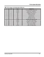
Page 94: ...88 Grain Bag Unloader OM Parts Identification GBU10 Top Auger with Adjustable Deflector 1 2 3 4 5 6 7 4 8 4 4 5 12 4 11 5 4 4 10 3 5 4 2 9 13 4 14 14 ...

Page 95: ...LG 3 4 N28442 SPACER 532 ID X 75OD X 37 4 13 4068 WASHER 1 2 SAE FLAT 5 6 4054 NUT LOCK 1 2 TOP 6 2 4052 NUT LOCK 3 8 7 2 4369 WASHER 5 16 FLAT 8 2 N29837 BOLT SHLD 1 2 X 5 8 9 1 201596 DIVERTER GBU SPOUT BOTTOM 10 2 N29075 NUT LOCK 1 2 SER FLANGE 11 1 N30999 CYLINDER 1 X 4 HYD 10 COMP 12 1 4154 BOLT 1 2 X 3 1 2 GRADE 5 13 1 4554 BOLT 1 2 X 6 1 2 GR 5 14 3 N21365 CLAMP 3 8 DOUBLE HOSE ...

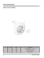
Page 96: ...Bag Unloader OM Parts Identification QTY PART DESCRIPTION 1 4 4986 BOLT CARRIAGE 1 2 x 12 GR 5 2 1 N22736 TIRE GBU DUAL OPTION 3 4 4068 WASHER 1 2 SAE FLAT 4 4 4054 NUT LOCK 1 2 GBU Dual Tire Kit N22753 1 2 3 4 ...

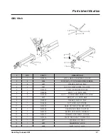
Page 97: ...1 x 6 FN TH GR 8 7 2 N16700 NUT 1 14 GR 8 FINE THREAD TOP LOCK 8 1 4577 BOLT 3 4 x 5 FN TH GR 8 9 1 N35327 WASHER FLAT 3 4 SAE 10 1 N16352 NUT LOCK 3 4 FN THRD 11 1 N37474 BASE CAT 2 BOLT ON REC HITCH 12 1 N37463 CLEVIS CAT 2 BOLT ON HITCH 13 1 N37475 BLOCK CAT 2 BOLT ON REC V 14 2 N37477 CUSHION CAT 2 BOLT ON REC 15 1 N37476 PLATE CAT 2 BOLT ON REC TOP 16 1 4071 WASHER 3 4 FLAT 17 1 4287 WASHER 3...

Page 98: ...92 Grain Bag Unloader OM ...

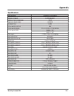
Page 99: ...Degrees Main Auger Drive Chain 80 Oil Bath Gearboxes Common US Made 50 Gearbox Lubricant 24 oz SAE 80W 90 Gear Lube 90 Gearbox Lubricant 24 oz SAE 80W 90 Gear Lube Bag Roller Accepts 9 Ft 10 Ft Bags Bag Roller Control Hydraulic Bag Roller Lock Automatic Latch Bag Roller Shaft 2 In Bag Roller Spindles Standard Bag Roller Sprockets Standard Bag Roller Tube 16 Ft with Hooks Adjustable Bag Knife 1 Pie...

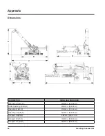
Page 100: ...in 513 28 cm Roller Operating Width B 208 24 in 528 92 cm Operating Width C 278 59 in 707 62 cm Operating Length D 255 82 in 649 78 cm Transport Height E 98 08 in 249 12 cm Transport Width F 100 90 in 256 29 cm Transport Length G 263 20 in 668 53 cm Dimensions Appendix A B C E F G D ...

Page 101: ...95 Grain Bag Unloader OM Torque Specifications Inches Hardware and Lock Nuts Appendix ...

Page 102: ...96 Grain Bag Unloader OM Appendix Torque Specifications Cont d Metric Hardware and Lock Nuts ...

Page 103: ......

Page 104: ...www loftness com Loftness Specialized Equipment Inc 650 So Main Street PO Box 337 Hector MN 55342 Tel 320 848 6266 Fax 320 848 6269 Toll Free 1 800 828 7624 Printed in USA Loftness 2019 ...

Reviews: