background image

L o g a n   G r a p h i c   P r o d u c t s   I n c . ,   1 1 0 0   B r o w n   S t r e e t ,   Wa u c o n d a ,   I L   6 0 0 8 4   To l l   F r e e   1   8 0 0   3 3 1   6 2 3 2     w w w. l o g a n g r a p h i c . c o m

1

FRAMER'S 

EDGE

C O U T E A U X   À   PA S S E - PA R T O U T  

MODÈLES 650, 655 ET 660

C O R TA D O R   D E   L Á M I N A   P E R I M É T R I C A  

MODELOS 650, 655 Y 660

PA S S E PA R T O U T S C H N E I D E R  

MODELLE

650, 655 & 660

TA G L I E R I N E   P E R   PA S S E PA R T O U T  

MODELLI 650, 655 E 660

TABLE DES MATIÈRES:

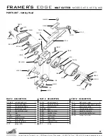
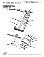
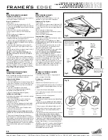
Découvrez votre système de découpe « Framer’s Edge » et identifiez les composants de l’appareil

Installation et orientation
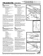
A. Déballage

4

B. Plan de travail et orientation

4

C.  Montage des conduits pour le rail parallèle

4

D. Fixation des bras d’équerrage

4

E. Installation du rail parallèle

5

F. Installation de la lame de la tête de découpe à 45 ° (biseau) 

5

G. Installation de la lame de la tête de découpe à 90° (coupe droite) 

5

H. Fixation de la butée mobile

6

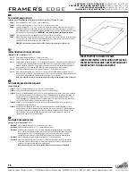
I.  Utilisation de la feuille doublure

6

Comment découper un passe-partout

A. Coupe droite d’un passe-partout à la dimension voulue

7

B. Découpe d’une fenêtre avec biseau en utilisant les lignes de repère

8

C. Découpe d’une fenêtre avec biseau en utilisant les butées de production multiples

9

Réglages et entretien

A. Réglage de la profondeur de la lame – tête de découpe à biseau

10

B. Réglage de la profondeur de la lame pour couper un passe-partout à 8 couches

10

C. Réglage de la pointe de la lame

10

D. Vis de compensation de surcoupe

11

E. Réglage de la profondeur de la lame – tête de découpe à 90°

11

F. Remise d’équerre du bras d’équerrage

12

G. Réajustement du rail parallèle

13

H. Démontage et remplacement des roulements

13/14

Guide pour faire des passe-partout créatifs

A. Double passe-partout

15

B. Passe-partout à coins décalés

16

C. Passe-partout encastré

17

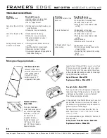
Problèmes et solutions

18

ÍNDICE DE CONTENIDO:

Aprendiendo a conocer el Cortador de Lámina Perimétrica Framer’s Edge y a identificar los componentes de la máquina

Instalación y Orientación

A. Desempaque

4

B. Superficie de trabajo y orientación

4

C. Instalación de los canales guía de la lámina perimétrica

4

D. Unir los brazos de escuadra

4

E. Instalación de la guía de la lámina perimétrica

5

F. Instalación de la cuchilla - cortador de bisel 

5

F. Instalación de la cuchilla - cortador recto

5

H. Unir el tope movible

6

I.  Utilice una hoja de respaldo.

6

Cómo Cortar una Lámina Perimétrica

A. Corte recto de una plancha de lámina perimétrica a la medida

7

B. Corte de una abertura biselada utilizando líneas marcadas

8

C. Corte de una abertura biselada utilizando topes de producción

9

Ajustes Y  Mantenimiento

A. Ajuste de la profundidad de la cuchilla - corte de bisel 

10

B. Ajuste de la profundidad de la cuchilla para cortar el tablero de lámina perimétrica 8-ply 10
C. Ajuste de la punta de la cuchilla

10

D. Tornillos de ajuste del sobrecorte

11

E. Ajuste de la profundidad de la cuchilla - corte recto 

11

F. Volver a poner a escuadra el brazo de escuadra

12

G. Volver a poner en paralelo la guía de la lámina perimétrica

13

H. Retiro y reemplazo del cojinete

13/14

Guía de Láminas Perimétricas Creativas

A. Lámina Perimétrica Doble

15

B. Lámina Perimétrica de Esquina Desplazada

16

C. Lámina Perimétrica de Embutir

17

Solución de Fallas

18

INHALTSVERZEICHNIS:

Einführung in die Bedienung des Framer’s Edge Passepartoutschneiders, Kennzeichnung der Geräteteile

Zusammenbau und Ausrichtung des Gerätes

A. Prüfen des Verpackungsinhalts

4

B. Arbeitsoberfläche und Ausrichtung des Gerätes

4

C. Installieren der Schienen für die Passepartoutführung

4

D. Anbringen des Anschlagarms

4

E. Installieren der Passepartoutführung

5

F. Einlegen der Klinge in den Schrägschitt-Schneidkopf

5

G. Einlegen der Klinge in den Geradeschnitt-Schneidkopf

5

H. Anbringen des Schiebestopps

6

I.  Verwenden eines Unterlagekartons

6

Schneiden eines Passepartouts

A. Gerades Zuschneiden auf ein Außenmaß

7

B. Schneiden eines Fensterausschnitts mit Schrägkante anhand von Markierungslinien

8

C. Schneiden eines Fensterausschnitts mit Schrägkante mit Hilfe von Produktionsstopps

9

Einstellungen und Pflege

A. Einstellung der Klingentiefe des Schrägschnitt-Schneidkopfes

10

B. Einstellung der Klingentiefe für 8lagige Passepartoutkartons

10

C. Einstellung der Klingenspitze

10

D. Einstellung der Überschnittknöpfe

11

E. Einstellungungen der Klingentiefe des Geradeschnitt-Schneidkopfes

11

F. Einstellen der Rechtwinklingkeit des Anschlagarms

12

G. Parallelstellen der Passepartoutführung

13

H. Entfernen und Ersetzen der Gleitlager

13/14

Kreatives Passepartoutschneiden

A. Doppelpassepartouts

15

B. Passepartoutzuschnitt mit Treppenschnitt

16

C. Passepartouteinleger

17

Mögliche Fehlerquellen und ihre Behebung

18

INDICE:

Imparare a conoscere la taglierina per Bordatrice e identificarne i componenti

Montaggio e orientamento

A. Disimballaggio

4

B. Piano di lavoro e orientamento

4

C. Installazione dei canali di guida del passepartout

4

D. Fissaggio dei bracci di squadratura

4

E. Installazione della guida del passepartout

5

F. Installazione della lama sulla taglierina per tagli a smusso

5

F. Installazione della lama sulla taglierina per tagli diritti

5

H. Fissaggio dell’arresto mobile

6

I. Utilizzo del foglio di rinforzo

6

Come tagliare un passepartout

A. Taglio diritto a misura di un cartoncino 

7

B. Taglio di un’apertura a smusso usando linee tracciate   

8

C. Taglio di un’apertura a smusso usando arresti di produzione

9

Regolazioni e manutenzione

A. Regolazione della profondità della lama sulla taglierina per tagli a smusso

10

B. Regolazione della profondità della lama per tagliare un cartoncino composto 

da 8 strati di compensato

10

C. Regolazione della punta della lama

10

D. Viti di regolazione per tagli irregolari

11

A. Regolazione della profondità della lama sulla taglierina per tagli diritti

11

F. Ripristino della squadratura del braccio di squadratura

12

G. Ripristino del parallelismo della guida del passepartout 

13

H. Rimozione e sostituzione del cuscinetto

13/14

Guida alla decorazione creativa del passepartout

A. Passepartout doppio

15

B. Passepartout con angoli inversi

16

C. Passepartout a intarsio

17

Localizzazione guasti

18

Summary of Contents for 650 Framer's Edge

Page 1: ...ction stops 9 27 squaring arms plus dual straight and bevel cutting heads P R O F E S S I O N A L S E R I E S For best results use only authentic Logan blades Logan Graphic Products Inc 1100 Brown Street Wauconda IL 60084 Phone 847 526 5515 Fax 847 526 5155 Toll Free 800 331 6232 L618N3 6 05 Email cs logangraphic com Model 650 Framer s Edge 40 mat cutter Model 655 Framer s Edge 48 mat cutter Model...

Page 2: ... from the date of original purchase Logan warrants that it will either repair or replace in its sole discretion any necessary replacement parts found to be defective Should the product need to be returned to Logan for repair or replacement parts authorization for any return must come from Logan Costs of returning the product to Logan including insurances shall be borne by the purchaser Logan shall...

Page 3: ...ar and contains both bevel and straight cutting blade holders 12 Bevel Cutter Holder 45 Degree Bevel Blade Holder 13 Straight Cut Blade Holder 90 Degree straight cut blade holder with lock down pin 14 Movable Production Stop Movable stop which connects to cutting head Allows fast production cutting of mat board 15 8 Ply Setting Adjustment screw used to set bevel cutting head to cut 8 ply thickness...

Page 4: ...c 1100 Brown Street Wauconda IL 60084 Toll Free 1 800 331 6232 www logangraphic com 3 FRAMER S EDGE MAT CUTTER MODELS 650 655 660 1 2 3 4 5 6 7 8 9 10 11 12 13 14 15 16 17 17 21 19 20 22 18 IDENTIFICATION OF MACHINE COMPONENTS ...

Page 5: ...e Always store flat The procedure detailed in the following instructions refer to the right and left side and the top and bottom of the mat cutter as shown Fig 2 C Installing Mat Guide Channels Putting the rounded end in towards the center of the board press each Mat Guide channel into the base board lining up the holes in the channels with the holes in the board Stand the base board up on its edg...

Page 6: ... to line up with the screw G Blade Installation Straight Cutter With the handle bar in the down position pull out on the lock down pin and rotate the blade holder as far back as it will go Loosen the blade holding screw and slide one 269 blade into the blade holder as far back as it will go Re tighten the blade holding screw Rotate the blade holder back to the neutral position Fig 7 E Installing M...

Page 7: ...rd which is at least as long as the mat you are cutting and at least 4 wide Your first Backing Sheet is included The Backing Sheet will need to be changed periodically Helpful Hint Move the Backing Sheet slightly after each cut to avoid cutting into previous scores that may cause the blade to flare out causing a curve in your cut Fig 9 H Attach the Movable Stop Arm Slide the Movable Stop Arm onto ...

Page 8: ...cking the blade holder into cutting position Fig 3 4 Holding the blade holder as shown in Fig 4 pull the cutting head directly towards yourself until the mat board is completely cut 5 IMPORTANT After finishing the cut make sure you pull the lock down pin out to allow the blade holder to go back to the neutral position Fig 5 Helpful Hints 1 After the lock down pin has locked the blade holder into c...

Page 9: ...utting head into position so that the edge of the metal near the green dot on the indicator plate is directly over the marked line Fig 3 6 Rotate the bevel blade holder down completely to seat the blade into the mat TIP Hold the cutting head firmly enough to not allow it to creep forward when first inserting the blade which will produce an overcut Fig 4 Maintaining downward pressure pull the cutti...

Page 10: ...you wish to cut Fig 3 6 Slide the cutting head into position in front of the top edge of the mat board As the movable stop approaches the edge of the mat board press down on the stop foot with your left index finger until it gently makes contact with the top edge of the mat Fig 4 7 Holding the stop foot in place with your finger rotate the blade holder down to enter the blade into the mat TIP Hold...

Page 11: ...der marked 8 ply setting Fig A 3 Insert Logan 268 8 Ply Blade Notice the blade has a bevel on only one edge Be careful to insert blade so bevel shows Re tighten the blade holding screw Note 268 blade can only be used on one corner bevel edge showing It will not operate properly installed with the opposite edge showing Fig 1 Fig A Straight Depth Adjustment Screw Bevel Edge Depth Adjustment Screw C ...

Page 12: ...n the side of the straight cut head use screwdriver provided to turn screw Fig 5 Remove blade and tighten desired screw DO NOT OVER TIGHTEN Replace blade and tighten knob Standard setting both screws loosened 3 16 setting bottom 3 16 screw 3 8 screw loose 3 8 setting bottom 3 8 screw 3 16 screw loose Fig 5 Fig 3 D Overcut Screw Adjustments NOTE These adjustments are only for when the production st...

Page 13: ...ar and down against the squaring arm Look to see if there are any gaps between the carpenter s square and the squaring arm If so the squaring arm needs to be adjusted Fig 6 TO RE SQUARE 1 By looking at where the gap is you can determine which way the squaring arm needs to go in order to be square again 2 Remove the squaring arm and locate the three screws inside of the slot 3 Adjust only two screw...

Page 14: ...between the Mat Guide and the Cutting Bar Fig 9 4 Slide the Mat Guide against the straight edge and the Guide Rail Make sure both the Mat Guide and the Guide Rail are making solid contact on both sides of the straight edge 5 Re tighten the Black Knobs first 6 Then re tighten the four screws Do another parallel test to ensure that the Mat Guide is now parallel H Bearing Removal Replacement Addition...

Page 15: ... MOLDED INTO THE BEARINGS FACE TOWARD THE CENTER OF THE CUTTING HEAD Fig 11 2 Now place a piece of 600 grit silicon carbide paper supplied on a flat even surface and gently sand away a small amount of the exposed bearing surface 3 After removing some of the bearing surface try the Cutting Head on the Cutting Bar It should fit tightly NOTE THIS IS A TRIAL AND ERROR METHOD OF BEARING REPLACEMENT DO ...

Page 16: ... line closest to the center of the mat Using the same procedure cut all four sides IMPORTANT At this point the fallout will not drop from the window Step 4 Remove the mat and reset the Mat Guide to 2 Reinsert the mat Step 5 Line up the silver indicator line on the Bevel Cutting Head with the drawn pencil line furthest from the center of the mat Cut until the silver indicator line lines up with the...

Page 17: ...squaring arm stop 135 handle bar 153 2 mat guide 203 N screw 211 handle bar screw 216 set screw 221 end cap 222 bumper 602 N mat guide slide 603 N mat guide wedge 604 mat guide screw 608 N1 cutting board 610 M mat guide scale 616 squaring arm screw 730 N cutting bar scale 1004 mat guide channel 1025 N mat guide channel screws PART DESCRIPTION PART DESCRIPTION PART DESCRIPTION 104 N 106 7 730 N 113...

Page 18: ...143 N indicator gauge 1 L146 N movable stop leg 1 L147 N lock down pin 1 L202 204 post 1 L206 N blade tip screw 2 L207 N bearing screw 4 L208 N cover screw 1 L112 F stop screw 1 L220 N blade screw 2 L241 N scale bar screw 1 L242 e ring 1 L273 blade cover screw 2 L430 A straight cut blade depth screw 3 L613 bevel return spring 1 L614 straight return spring 1 L730 N movable stop scale 1 L865 N bevel...

Page 19: ... center of the cutting head Blade is dull More great Logan products 708 Extension Table Laminate surface board extension that mounts on to 650 655 or 660 mat cutters Allows border sizes up to 17 using parallel mat guide Logan Surface V Groover Offers a way to cut surface V Grooves quickly and accurately with zero overcuts Push Pull action cuts V Grooves right on the surface of the matboard elimina...

Page 20: ...ons Complete and detailed directions featuring Logan s picture framing tools system Learn inside secrets from professional framers for creating your own custom framed art Home Picture Framing Model F245 Also available are 3 different books on matting and framing by Vivian C Kistler CPF Basic Mat Cutting Model 238 M Mat Decoration Book Model 240 M Do It Yourself Picture Framing Model 241 M See your...

Page 21: ...ondo del pannello Para mejores resultados utilice solamente las cuchillas auténticas de Logan Per ottenere i migliori risultati usare solamente lame Logan originali Für optimale Schneidergebnisse Verwendung von Logan Originalklingen empfohlen Pour de meilleurs résultats n utilisez que les lames Logan d origine MANUEL D INSTRUCTIONS ET D UTILISATION Système de découpe de passe partout de qualité pr...

Page 22: ...de temps à en prendre connaissance dès le début il répondra à un grand nombre de questions que vous vous poserez pendant son utilisation Vous verrez que le temps que vous aurez passé ne sera pas perdu et que vous serez alors très vite en mesure de découper des passe partout de qualité REMARQUE Ce mode d emploi concerne l installation et les instructions d utilisation des modèles Framer s Edge suiv...

Page 23: ...Retiro y reemplazo del cojinete 13 14 Guía de Láminas Perimétricas Creativas A Lámina Perimétrica Doble 15 B Lámina Perimétrica de Esquina Desplazada 16 C Lámina Perimétrica de Embutir 17 Solución de Fallas 18 INHALTSVERZEICHNIS Einführung in die Bedienung des Framer s Edge Passepartoutschneiders Kennzeichnung der Geräteteile Zusammenbau und Ausrichtung des Gerätes A Prüfen des Verpackungsinhalts ...

Page 24: ...e recto 21 Ajuste de Sobrecorte de la Parte Baja Para ajustar el sobrecorte en la parte baja de la lámina perimétrica 22 Ajuste del Sobrecorte de la Parte Alta Para ajustar el sobrecorte en la parte alta de la lámina perimétrica 23 Cuchillas Fig 1 página 5 Cuchilla de doble bisel 269 utilizada para cortar el tablero de lámina perimétrica de grosor estándar Cuchilla de bisel simple 268 utilizada pa...

Page 25: ...5 ET 660 CORTADOR DE LÁMINA PERIMÉTRICA MODELOS 650 655 Y 660 PASSEPARTOUTSCHNEIDER MODELLE 650 655 660 TAGLIERINE PER PASSEPARTOUT MODELLI 650 655 E 660 1 2 3 4 5 6 7 8 9 10 11 12 13 14 15 16 17 17 21 19 20 22 18 IDENTIFICATION DES COMPOSANTS DE L APPAREIL IDENTIFICACIÓN DE LOS COMPONENTES DE LA MÁQUINA KENNZEICHNUNG DER GERÄTETEILE IDENTIFICAZIONE DEI COMPONENTI ...

Page 26: ...de Escuadra antes de apretar los tornillos Fig 4 ZUSAMMENBAU UND AUSRICHTUNG DES GERÄTES A Prüfen des Verpackungsinhalts Entfernen Sie das Füllmaterial und heben Sie das Framer s Edge Passepartoutschneidegerät aus dem Transportkarton BEWAHREN SIE DIE VERPACKUNG AUF Entnehmen Sie die Tüte mit den Geräteteilen und prüfen sie den Inhalt Abb 1 a Anschlagstopp b Anschlagarm 68 cm c Produktionsstopp 1 d...

Page 27: ... la cuchilla de vuelta a la posición neutral Fig 7 E Installieren der Passepartoutführung Zum Einlegen der Passepartoutführung lösen Sie die zwei schwarzen Knöpfe mit drei vollen Umdrehungen Mit dem breiteren Rand der Passepartoutführung in Richtung Schneidschiene fassen Sie die Passepartoutführung so dass Ihre Daumen etwas Druck auf die Knöpfe ausüben Richten Sie die Schieber der Passepartoutführ...

Page 28: ...e necesitará cambiar la Hoja de respaldo periódicamente Datos Útiles Mueva la Hoja de Respaldo levemente después de cada corte para evitar cortar en las huellas de cortes anteriores que puedan hacer que la cuchilla se expanda causando una curva en su corte Fig 9 H Anbringen des Schiebestopps Bringen Sie den Schiebestopp wie in der Abbildung gezeigt mit dem Federfuß nach unten auf dem Skalabalken a...

Page 29: ... hacia abajo sobre la barra de la manija al cortar Esto puede hacer que la cabeza de corte se eleve saliéndose del tablero de lámina perimétrica y no corte hasta el fondo a través del material NOTA Su cortador de lámina perimétrica Framer s Edge ha sido pre ajustado para el corte recto de tableros de lámina perimétrica de grosor estándar Para cortar un material más grueso usted debe hacer un ajust...

Page 30: ...la manija a una posición vertical 8 Gire la lámina perimétrica _ de vuelta hacia la derecha y asegúrese que la lámina perimétrica esté contra el brazo de escuadra y contra la guía de la lámina perimétrica de la izquierda 9 Continúe los pasos 5 a 8 hasta que estén cortados los cuatro lados RECOMENDACIÓN No empuje hacia abajo la barra de la manija al cortar esto doblará la barra de corte hacia arrib...

Page 31: ...segúrese que la lámina perimétrica esté contra el brazo de escuadra y contra la guía de la lámina perimétrica de la izquierda 10 Continúe los pasos 6 a 9 hasta que estén cortados los cuatro lados RECOMENDACIÓN No empuje hacia abajo la barra de la manija al cortar esto doblará la barra de corte hacia arriba y evitará que la cuchilla corte a través del tablero de la lámina perimétrica C Schneiden ei...

Page 32: ...en drücken Sie das Klingenmagazin durch und verschieben Sie es Beobachten Sie die Position der Klingenspitze Wenn Sie die Schiene leicht berührt muss sie nicht verstellt werden Wenn diese Berührung zu stark ist bzw wenn keinerlei Kontakt vorhanden ist verstellen Sie die Klingenschraube entsprechend Drehen Sie die Schraube nur um jeweils eine viertel Drehung und testen Sie die Position erneut damit...

Page 33: ...jetador de la cuchilla de corte recto 2 Tornillos de Profundidad de 3 16 o de 3 8 Ubicados en el lado de la cabeza del corte recto use el destornillador provisto para girar el tornillo Fig 5 Quite la cuchilla y apriete el tornillo deseado NO APRIETE EXCESIVAMENTE Reemplace la cuchilla y apriete la perilla Ajuste estándar ambos tornillos aflojados Ajuste de 3 16 Tornillo bajo 3 16 tornillo 3 8 suel...

Page 34: ...rnillo A hacia adentro en el sentido de las agujas del reloj un cuarto de vuelta Fig 7 4 Reinstale el brazo de escuadra y compruebe la escuadra Haga los ajustes adicionales hasta que esté a escuadra F Einstellen der Rechtwinkligkeit des Anschlagarms BENÖTIGTE WERKZEUGE Schraubenzieher Zimmermannswinkel ACHTUNG Es passiert relativ häufig dass man Passepartoutkartons geliefert bekommt die nicht exak...

Page 35: ...befinden Delrin fängt die natürliche Abnutzung auf und macht kostenaufwendige Materialersetzungen und ständiges Ölen der Metallteile unnötig Logan liefert die Gleitlager für die gesamte Laufzeit der Maschine kostenlos Bitte setzen Sie sich diesbezüglich mit Ihrem Händler in Verbindung G Ripristino del parallelismo della guida del passepartout UTENSILI NECESSARI cacciavite per viti con taglio a cro...

Page 36: ...ERROR PARA REEMPLAZAR EL COJINETE NO LIJE EXCESIVAMENTE LOS COJINETES 4 En este punto compruebe la relación de la punta de la cuchilla con el borde de la Barra de Corte Si la cuchilla golpea la Barra de Corte antes de que alcance el extremo de la barra entonces tiene que quitarse más superficie del cojinete del LADO RECTO de los cojinetes Fig 12 Al contrario si la cuchilla NO golpea el borde de la...

Page 37: ... 1 2 x 9 1 2 Paso 4 Fije la segunda lámina perimétrica CARA HACIA ABAJO en el dorso encintado de la primera lámina perimétrica asegurándose que esté centrada razonablemente bien Paso 5 Ajuste la Guía de la Lámina Perimétrica a 2 1 4 y corte la segunda abertura La doble pieza que sale caerá de la ventana y la lámina perimétrica estará terminada y perfectamente alineada NOTA Se pueden lograr láminas...

Page 38: ... Stop Markierung mit der oberen Hilfslinie übereinstimmt die sich am weitesten entfernt von der Mitte des Passepartouts befindet Schneiden Sie gemäß dieser Vorgehensweise alle vier Seiten WICHTIG Halten Sie das Reststück des Fensterausschnitts gut fest bevor Sie das Passepartout drehen um den letzten Schnitt durchzuführen PASSEPARTOUT CON ANGOLI INVERSI Esempio 8 x 10 con apertura 7 x 5 Procedura ...

Page 39: ...e Schritt 5 Entfernen Sie das Innenstück des Fensterausschnitts des zweiten Passepartouts und legen Sie das innere Randstück des ersten Zuschnitts in den Fensterausschnitt des zweiten Zuschnitts Die zwei Stücke sollten wie Puzzleteile exakt ineinander passen und auf der Vorderseite eine glatte Oberfläche ergeben LÁMINA PERIMÉTRICA CON RELLENO Ejemplo 8 x 10 con abertura 5 x 7 Paso 1 Ajuste la Guía...

Page 40: ... de la manija al cortar Cojinetes gastados La máquina no está en una superficie a nivel Problema Cabeza de corte dura para jalar al cortar Razones Posibles Profundidad de la cuchilla graduada muy hondo No quitó la hoja de respaldo durante el corte recto No está jalando desde el centro de la cabeza de corte La cuchilla está embotada Problem Ausgefranster Schrägschnitt Mögliche Ursache Kein Unterlag...

Page 41: ...8 10 mm Comprende tre lame di ricambio Logan Surface V Groover permet de découper des rainures en V rapidement et précisément sans surcoupe L action pousser tirer découpe des rainures en V directement sur la surface du passe partout sans besoin de détourage ou de collage Fonctionne entièrement avec des butées Logan V Groover couteau pour rainurer en V modèle 705 Lames de rechange modèle 1258 Ranur...

Page 42: ...werke gekonnt einrahmen können Home Picture Framing Modell 245 Informazioni complete e dettagliate sugli attrezzi di incorniciatura Logan Scoprite i segreti dei corniciai professionisti per realizzare le vostre cornici personalizzate Come realizzare cornici a casa propria Modello 245 Aussi disponibles trois livres de Vivian C Kistler CPF sur la réalisation de passe partout et d encadrements Basic ...

Page 43: ...60084 Toll Free 1 800 331 6232 www logangraphic com FRAMER S EDGE COUTEAUX À PASSE PARTOUT MODÈLES 650 655 ET 660 CORTADOR DE LÁMINA PERIMÉTRICA MODELOS 650 655 Y 660 PASSEPARTOUTSCHNEIDER MODELLE 650 655 660 TAGLIERINE PER PASSEPARTOUT MODELLI 650 655 E 660 ...

Reviews: