Instruction Manual
Model F100-2
PRO SAW
1
Logan Graphic Products Inc., 1100 Brown Street, Wauconda, IL 60084 Toll Free 1 800 331 6232 www.logangraphic.com
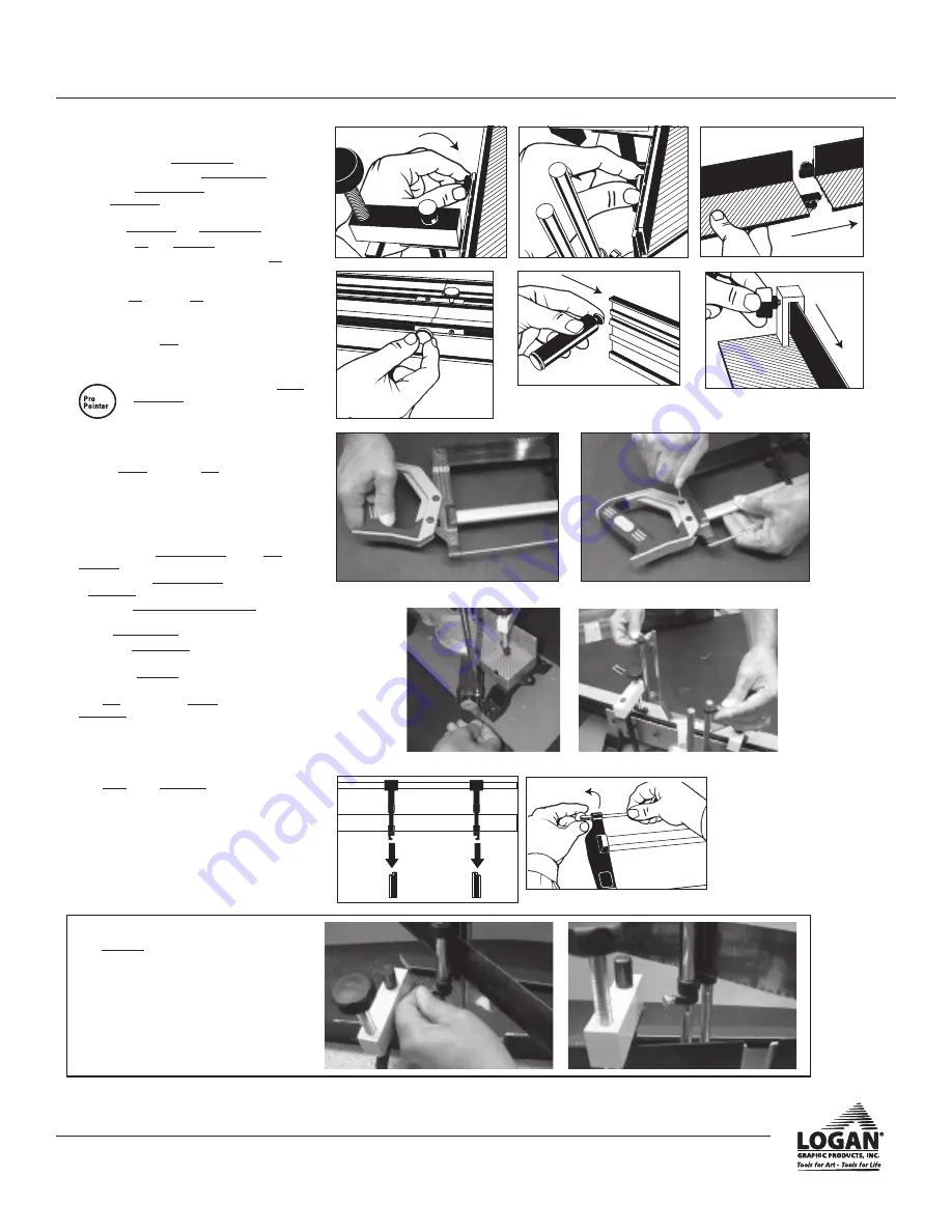
Fig. 6
Fig. 5
Assembly Procedure
A. Fence
1.
Tighten both rear thumb screws (Fig. 1 & 2).
2.
Repeat steps 1 and 2 for left hand fence.
3.
To attach extension fence, feed the fence section
into connectors extending from one another (Fig.
3).
4.
Tighten connectors with thumb screws (Fig. 4).
5.
To attach leg, turn saw base on it’s side.
6.
Loosen screw on support leg, then slide leg with
screw tab attached into channel of fence exten-
sion to the desired position (Fig. 5).
7.
Tighten leg by turning leg until secure.
B. Stop
1.
Slide moulding stop onto fence (Fig. 6).
2.
Tighten knob to lock.
Mounting-Optional
•
Mount base board to table using mount-
ing screws supplied. Drill 1/4” (6mm)
pilot holes for bolts.
C. Handle
1.
Be sure not to lose the two nuts.
2.
Slide handle onto end of saw and line up the bolt
holes (Fig. 6).
5.
Using Allen Wrench, tighten screws to secure
handle (Fig. 8).
D. Saw
1.
To insert the four saw guide posts into the saw
assembly:
a. Place the four saw guide posts into position on the
angle pivot.
b. Insert the guide post assembly screws with the
screwhead facing outward in the slot in front of
each saw guide post.
c. Using the Allen wrench, tighten the screw heads
(Fig. 9).
2.
To install the saw rests, slide one each onto both the
front right and back left guide posts (Fig. 10).
3.
Slide saw onto rods with handle onto same side as
angle pivot handle (Fig. 11).
E. Blade Changing
1.
Loosen tension knob but do not totally remove (Fig.
12).
2.
Slide blade free of guide bars.
3.
Reverse steps 1-3 for replacing with new blade.
Note: Be sure blade teeth are angled pointing away
from handle.
Fig. 1
Fig. 2
Fig. 4
Fig. 3
✔
Fig. 11
Fig. 12
Saw rests explained.
The saw rests are an added feature to raise the
saw out of the way while the moulding is being
positioned.
To use the rests, first raise the saw upward on the
guideposts. Next, slide the saw rests upward on
the guidepost into position and tighten the screw.
Fig. 7
Fig. 8
Fig. 10
Fig. 9


