SPACE 2000 (T and M versions) OPERATION MANUAL
27
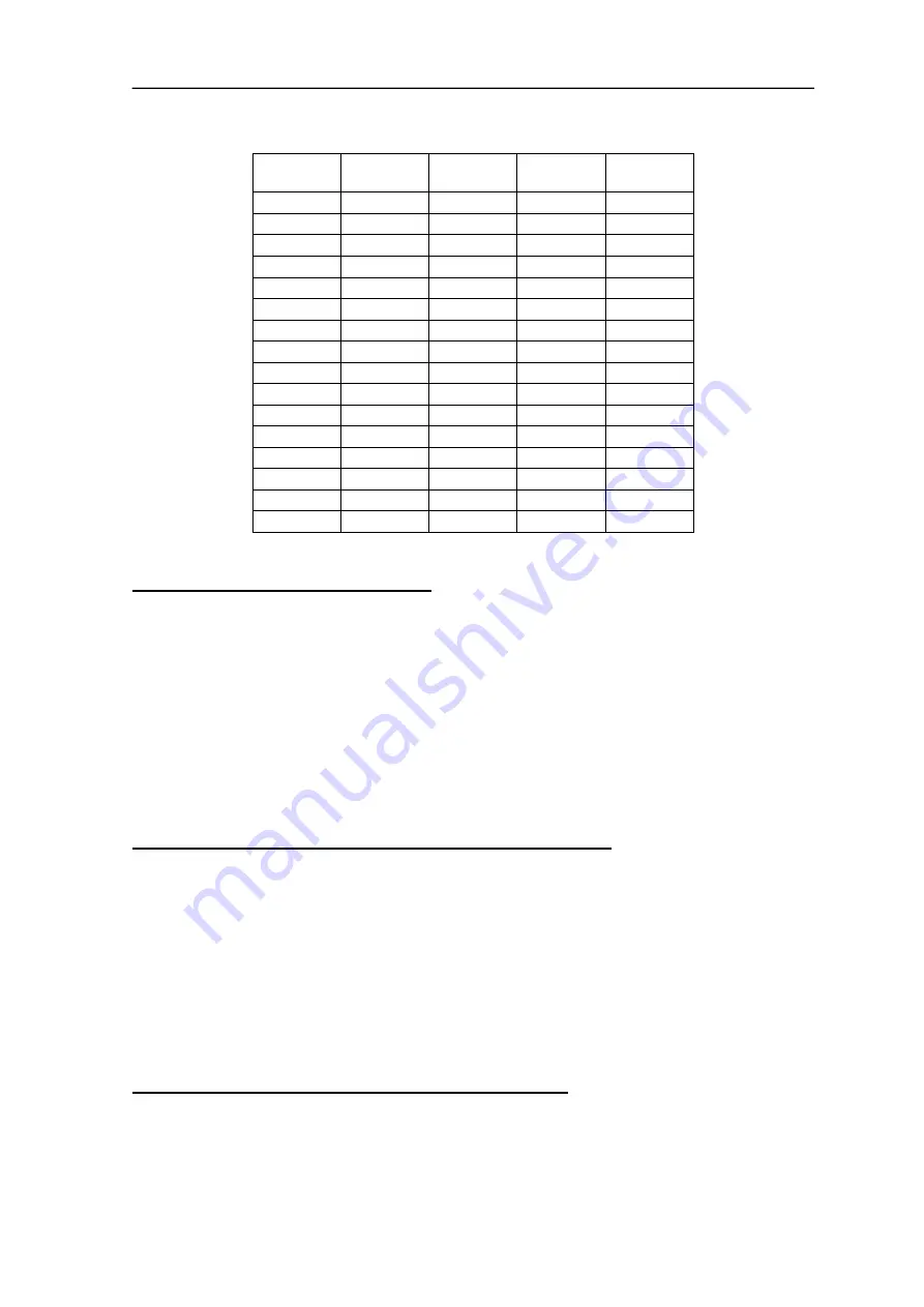
“P04”
VALUE
START BIT
BIT no.
PARITY
STOP BIT
00
START
7 BIT DATA
----------
1 STOP
01
START
7 BIT DATA
----------
2 STOP
02
START
7 BIT DATA
EVEN
1 STOP
03
START
7 BIT DATA
EVEN
2 STOP
04
START
8 BIT DATA
----------
1 STOP
05
START
8 BIT DATA
----------
2 STOP
06
START
8 BIT DATA
EVEN
1 STOP
07
START
8 BIT DATA
EVEN
2 STOP
10
START
7 BIT DATA
----------
1 STOP
11
START
7 BIT DATA
----------
2 STOP
12
START
7 BIT DATA
ODD
1 STOP
13
START
7 BIT DATA
ODD
2 STOP
14
START
8 BIT DATA
----------
1 STOP
15
START
8 BIT DATA
----------
2 STOP
16
START
8 BIT DATA
ODD
1 STOP
17
START
8 BIT DATA
ODD
2 STOP
P05 = RS 232 serial line Baud rate
This defines the transmission speed to be used for adaptation to the peripherals to
which the serial line is connected (Personal Computer, Printers)
The values that can be set for this parameter are as follows:
0
=
38400 Baud
1
=
19200 Baud
2
=
9600 Baud
3
=
4800 Baud
4
=
2400 Baud
5
=
1200 Baud
6
=
600 Baud
P06 = Input enabling for the measurement tracer point
The measurement tracer point input is an optional that requires hardware
variations in the main board.
The values that can be programmed for this parameter are as follows:
0
=
Input for tracer point disabled
1
=
Input for tracer point enabled in operation mode “1”
2
=
Input for tracer point enabled in operation mode “2”
*
Contact LOGAN Technical Service for further details
P07 = Tracer point contact sphere diameter value
The value that can be programmed runs from 0000 to 9999.
The unit of measurement of the programmable value corresponds to the least
significant unit of the display format programmed. For example, if the format is
5.2, each unit is equal to 1 hundredth of a millimeter; if the format is 4.3, the same
unit is equal to one thousandth of a millimeter.


