background image

Programming System Features [continued]

Programming Guide

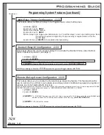
This function allows the you to restore all programming back to factory default. All programming and settings
will be deleted. PASSCODE not required to perform this programming function. This command should be
used only for critical situations where the system might require a reset. This command will erase all settings,
including phone numbers in memory.

1) Pick-up Phone Handset (listen for dial tone)  and ENTER

*#0

(Unit will be defaulted back to Factory Settings including the PASSCODE)

2)
3) ENTER
4) Listen for
5) WAIT FOR DIAL TONE
6) HANG-UP

Listen for

(2) Beeps

0#0

(2) Beeps for acceptance of programming.

(to be heard in the phone handset)

This feature allows the user to change their 4-Digit PASSCODE.

(FACTORY DEFAULT

)

1111

1) PRESS

Listen for

*10

2)

(1) BEEP.

(If a new 4 Digit code is not entered within 10 seconds then the previous programmed code will remain)

3) ENTER NEW (4 DIGIT) CODE

4) Listen for

____

(

for acceptance of programming.

2) Beeps

Page 16

Changing the 4-Digit PASSCODE

*10

RESETTING THE UNIT TO FACTORY DEFAULT SETTINGS

Continued

Summary of Contents for A202CR

Page 1: ... ON CanadaL4L8S9TollFree 1 888 790 5900E mail info logenex com Don t open your door to the unknown TeleDoorBellTM Installation Programming A202CR A204CR X S Series Audio Audio Video Day Night Camera TeleDoorBell Audio Stainless Steel ...

Page 2: ...types of phones and the loads LN they present to the overall system NOTE 3 Remote Call Answer may not be compatible with various types of add on phone features such as Ident A Call Call Display Long Distance ringing or any other feature s which will change or produce a different ringing pattern of an incoming call 4 System may not be compatible with various voice mails including cell phones when e...

Page 3: ... overload wall outlets and extension cords as this can result in risk of fire or electric shock 10 Never push objects of any kind into this product through cabinet slots as they may touch dangerous voltage points or short out parts that could result in a risk of fire or electric shock Never spill liquid of any kind on the product 11 To reduce the risk of electric shock do not dissemble this produc...

Page 4: ...el VC Day Night camera with ir n a in stainless steel Model Number Identification KIT A CR 2 2 Door 4 4 Door X Standard Unit Satin Nickel VC Day Night camera with ir n a in stainless steel Model Number Identification INDIVIDUAL DOORSTATION 20 ...

Page 5: ...l VC Day Night camera with ir Model Number Identification KIT A CR 2 2 Door 4 4 Door Model Number Identification INDIVIDUAL DOORSTATION 20 S F Flush Mount VC Day Night camera with ir S S S Surface Mount Stainless Steel F Flush Mount Page 3 ...

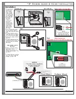
Page 6: ...or is by hanging up on the existing telephone call and then picking up the handset within the allowed 2 minutes at which point you will be automatically connected to the Door Station Speaker Beyond the two minute window you will have to manually activate the Door Station Speaker Door Station Speaker 1 Door Station Speaker 4 Note Speaker must be connected to a the port which you are trying to commu...

Page 7: ... 1 relay dry contact point for automated control capability To complete the installation the installer must supply install the following RJ31X CA38A This is recommended in the event that the controller needs to be disconnected This will provide a bypass capability whereby the telephone line continues to work if the unit needs to be removed from the telephone line Note If installation is done at a ...

Page 8: ...with doorstation 12V DC Output Ring On Off Relay Contacts Door Spkr 2 Door Spkr 1 Tele Line In Out Power Plug RJ11 Modular Wire Supplied with controller To Speaker Jack TeleDoorBell RCA Patch Cord supplied with Speaker To Video input or Cable Modulator DVR Monitor or Television Common GROUND 12VDC Video Video Wire can vary from standard quad CAT 5 and or RG6 for the Video Signal Speaker distance f...

Page 9: ...and VID See Fig 2 See Fig 3 See Fig 4 See Fig 5 See Fig 6 VIDEO MODEL SETUP supplied in kit To Speaker Terminal TeleDoorBell Fig 3 Fig 2 Side View Fig 2 Side view Wiring Hole TeleDoorBell Fig 5 Step 1 Mounting Holes IN IN VOLUME MIN MAX COMM Audio Connection IN IN Green Red Fig 4 NOTICE Volume Control may need to be adjusted to accommodate for different acoustic environments TeleDoorBell TeleDoorB...

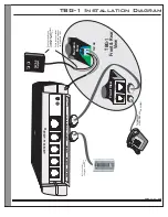
Page 10: ...rBellTM Figure 5 Spk Rly 1 Spk Rly 2 Spk Rly 3 Spk Rly 4 Tele Line In Out Power Plug A202CR A204CR Relay 1 connection Relay 3 connection 11 to activate 31 to activate or will automatically activates if configured as the DoorBell function Applicable for both A202 A204 Models NOTICE See Page 6 7 for Door Station Connectivity OUT OUT IN IN RJ31X CA38A Alarm Jack LINE from phone provider VOIP Modem or...

Page 11: ...telephone or KSU PBX phone system Existing Power Supply supplied with TeleDoorBell Controller speaker kit Splice the power cables and split them between the Controller TBG 1 RJ11 RJ45 Reverse View 16V AC Front View TBG 1 Front Rear View Spk Rly 4 Spk Rly 3 Spk Rly 2 Spk Rly 1 Tele Line In Out Power Plug ...

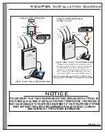
Page 12: ...e system configuration 3 To all the premise phones which do not require high speed internet connection which will eliminate the need to have DSL filters at every phone jack RJ45 RJ45 RJ45 PHONE SYSTEM KSU Note This DSL 3 PORT FILTER may cause a to occur This may result in the caller to partially hear the low level conversation between the home owner and the visitor at the door station when the cal...

Page 13: ... require a TBG 1 accessory module Page 9 TeleDoorBell OUT OUT IN IN RJ31X CA38A Data Jack Not supplied Tip Ring Phone System must be programmed for extensions to ring Consult your KSU PBX phone system manual for instructions Black Green Red Yellow Spk Rly 4 Spk Relay 3 Spk Relay 2 Spk Relay 1 Tele Line In Out Power Plug A202CR A204CR Spk Rly 4 Spk Relay 3 Spk Relay 2 Spk Relay 1 Tele Line In Out P...

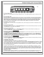
Page 14: ...Audio Out Connection Optional Audio Out on the back and front ONLY USE ONE OUTPUT ONLY 9 Switch to left for Contact Closure Switch to right for 12Volt trigger Muting Connection Muting Connection Output Muting Trigger Hi Fi Feature Operations On a door station call the TeleDoorBell will mute for 1 minute If the call is answered the system will remain muted for the duration of the call The TeleDoorB...

Page 15: ...e user has the ability to block specific phone numbers and or numbers that begin with a particular sequence eg or 1976 011 1 PRESS 2 Listen for 3 SELECT a Memory BIN Number 4 1 _ __ 2 BEEPS 0 9 1 to Listen for 1 BEEP 2 BEEPS will be heard for acceptance of programming Note Call restriction requires 3 digits minimum To restrict 1 long distance number you will have to enter To block any other one di...

Page 16: ...4 or more rings and an ALARM SYSTEM if present must be configured to answer on ANSWERING MACHINE OVERRIDE 1 1 MODE 1 PRESS Listen for 5 5 2 BEEPS 2 BEEPS 3 BEEPS 3 1 RINGING this means you call in for 3 rings hang up wait for 10 15 Seconds for the unit to ENABLE itself and then call back The unit at this point will answer on the first ring OFF Unit will not answer FACTORY DEFAULT NOTE By continuin...

Page 17: ...amming the Door Station Call Forwarding Phone 6 Continued Continued on Page 16 This feature allows you to program the relay s activation timing Relay timing setting can be from 0 5 seconds to 49 seconds latching or for closure upon door station button press 1 PRESS 8 2 Select RELAY you wish to program PRESS 3 Enter RELAY 2 Digit Timing Setting 4 Listen for 1 2 3 4 OR OR OR 2 BEEPS for acceptance o...

Page 18: ... for dial tone and ENTER 0 Unit will be defaulted back to Factory Settings including the PASSCODE 2 3 ENTER 4 Listen for 5 WAIT FOR DIAL TONE 6 HANG UP Listen for 2 Beeps 0 0 2 Beeps for acceptance of programming to be heard in the phone handset This feature allows the user to change their 4 Digit PASSCODE FACTORY DEFAULT 1111 1 PRESS Listen for 10 2 1 BEEP If a new 4 Digit code is not entered wit...

Page 19: ...he call is answered the system will remain muted for the duration of the call The will un mute once communication has ended TeleDoorBell TeleDoorBell On an incoming call the will mute on the first ring If the call remains unanswered after the third ring the will initiate a Ring Over Page feature for the remainder of the ring cycle TeleDoorBell TeleDoorBell Pick up hand set Press will activate muti...

Page 20: ... and power adapter confirm LED light is flashing 2 Check power connection into the unit 1 The unit may have locked up unplug the power adapter and reconnect after 10 seconds 2 Check for a short between the red and green wire going to door station 1 The red and green wire to the door station is either reversed has a short or has a break in connection verify this by plugging the door station in anot...

Page 21: ...one systems do not recognize s distinctive ring pattern PAGE 13 TeleDoorBell 1 The may not be an A204 model Please refer to model label on controller and or barcode on unit box TeleDoorBell 1 Call restriction may be enabled Please refer the programming section to clear memory bins 2 A factory reset may be required Please refer to programming section PAGE 13 PAGE16 1 Try reprogramming the call forw...

Page 22: ...e purchaser s time the claims of third parties including customers and injury to property This warranty contains the entire warranty and shall be in lieu of any and all other warranties whether expressed or implied including all implied warranties of merchantability or fitness for a particular purpose and of all other obligations or liabilities on the par of Logenex Innovations Inc Logenex Innovat...

Page 23: ...ere such actions are reasonable required and proper in its business Should any such changes render customer s terminal equipment incompatible with the telephone company facilities or any products installed Logenex Innovations Inc will not held responsible for any failures or problems which may occur as a result of such changes failures and or interruptions of the service Before installing this equ...

Page 24: ...Manufacturing Plant 6A 7500 Martin Grove Rd Woodbridge ON Canada L4L 8S9 Phone 905 790 8823 Toll Free 1 888 790 5900 E mail info ogenex com l www logenex com May 2008 ...

Reviews: