Controller Anatomy
Page 5
Fig 1
Spk/Rly#1
Spk/Rly#2
Spk/Rly#3
Spk/Rly#4
Tele Line In & Out
Power Plug
A202CR & A204CR
2
6
5
4
3
7
1
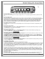
[1] Power Supply Jack
.
[2] Power Status LED
NOTE: When unit is first powered up the LED will remain solid for 5 seconds and will begin to flash slowly
when ready. When the TeleDoorBell is in use the LED will flash rapidly for the duration of connectivity.
[3] Telephone Line In & Out Jack
[4] Speaker / Relay Port #1
(RELAY #1)
[5] Speaker / Relay Port #2
(RELAY #2)
[6] Speaker / Relay Port #3
(RELAY #3)
[7] Speaker / Relay Port #4
(RELAY #4)
This jack is the connecting point for AC power supply to the unit. The supply is typically 16 VAC at a minimum of 250
mA
When "FLASHING" this LED indicates the presence of power to the unit and that the controller is operating properly.
When LED is "OFF" it indicates the absence of power to the unit. When the LED is “ON” (not flashing) this indicates that
the unit is locked up and will need to be reset by unplugging the power for 60 seconds and then powering back up.
This jack provides connection to the incoming telephone line on the inner pair and connection to telephone(s) on the
outer pair.
This port jack enables a connection to a
for communication while also providing (1) dry contact
relay
for automated control capability.
This port jack enables a connection to a
for communication while also providing (1) dry
contact relay
for automated control capability.
This port jack enables a connection to a
for communications while also providing (1) dry contact
relay
for automated control capability.
(see page9)
This port jack enables a connection to a
for communications while also providing (1) relay dry
contact point
for automated control capability.
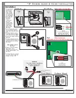
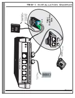
To complete the installation the installer must supply/install the following:
* RJ31X
CA38A
. (This is recommended in the event that the controller needs to be disconnected. This will
provide a bypass capability whereby the telephone line continues to work if the
unit needs to be removed
from the telephone line. Note: If installation is done at a location that has an existing alarm jack (RJ31X
CA38A)
then ensure that the alarm is installed before the TeleDoorBell RJ31X
CA38A jack. Otherwise, the alarm system
may not have disconnect priority.
Installation of the system requires that the installer install a 2-conductor wire 22 AWG (Max Length 1000’), from the
location of the door speaker unit to the location of the system control unit or a CAT-5 wire (Max Length 250’) if you are
installing a system with Video/Audio features.
It is recommended that the system control unit be installed near the point-of-
entry of the customer's main telephone line.
Door Station Speaker
“Door Station Speaker”
Door Station Speaker
**This RELAY is PRESET [DISABLED] to use RELAY#3 for the DOORBELL function, you must [ENABLE] the
DOORBELL Function in the programming. This Relay can be changed back to the standard control capability.
Doorbell function is applicable for both A202 & A204 models
“Door Station Speaker”
TeleDoorBell
Installation Instructions
and/or
(supplied)
and/or
and/or
NOTE: To achieve 1000 ft range with video, you must use COAX Cable in-place of
the 2 conductor required for the video signal.
IMPORTANT NOTICE:
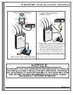
For added protection we strongly recommend you use surge protectors on both your power supply and on the C/O line (phone
line) to protect against lightning and other energy surges. This precaution may be extremely important in rural areas.
Model A204 ONLY
Model A204 ONLY


