Page 7
“S” Series Audio & Video Installation
Installation
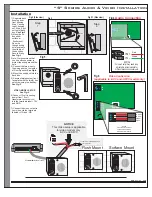
1) Separate back
housing from
front housing.
Step 1: swing
top of housing
out. Step 2: pull
unit out of back
box.
2) Mount back
box either
surface or
flush mount.
Run wire
though wiring
hole located in
the middle of
the back box.
Secure firmly.
Note: We recommend that
you use silicone sealer to
protect the wiring around the
hole
3) Connect the two wires to
the wiring post on the inside
of Door Speaker.
4) Mount the unit back into the
back box.
5) Secure stainless steel front
face plate with the two(2) hex
set screw using the hex key.
6)Connect 12 volt incoming
power from 12 volt
transformer
into the terminals label +12V
and GND.
7) Connect the video output to
your wires via the terminals
lVID and -VID.
See Fig-2
See Fig-3
See Fig-4
See Fig-5
See Fig-6
VIDEO MODEL SETUP
(supplied in kit)
To
Speaker Terminal
TeleDoorBell
Fig 3
Fig 2 (Side View)
Fig 2 (Side view)
Wiring Hole
TeleDoorBell
Fig 5
Step
1
Mounting Holes
+IN
-IN
VOLUME
MIN
MAX
COMM
Audio Connection
IN +
IN -
Green
Red
Fig 4
NOTICE
Volume Control may need to be
adjusted to accommodate for
different acoustic environments.
TeleDoorBell
TeleDoorBell
Flush Mount
Surface Mount
Step
4
Fig 2.1 (Side view)
12V
GND
+VID
-VID
+IN
-IN
POWER
VIDEO
VOLUME
MIN
MAX
COMM
12 Volt +
12 Volt -
Video +
Video -
NOTICE
Volume Control may need to be
adjusted to accommodate for
different acoustic environments.
Fig 6
Video Connection
(applicable to -SVC and -SFVC model only)
Spk/Rly#1
Spk/Rly#2
Spk/Rly#3
Spk/Rly#4
Tele Line In & Out
Power Plug
TeleDoorBell
“X Series”
TeleDoorBell
12VDC
Output
To Video input or Cable Modulator, DVR,
Monitor, or Television
NOTICE
This Video setup is applicable
for video models only.
-SVC and SFVC


