background image

Jump Settings 

1.


Motherboard Layout 


2.


Connector & Jumper Setting


DC1 

Mini Din 4P for Power Input Port 

DC2 

Internal Power Input Connector 

CD1 

RJ11 for Cash Drawer Port 

LAN1 

RJ45 for LAN Port 

USB1, 2 

USB dual stack for USB Port 

USB4, 5, 6, 7 

USB Connector 

COM1 

D-SUB 9 Pin for COM1 Port 

COM2 

D-SUB 9 Pin for COM1 Port 

COM3 

RJ48 for COM3 Port 


12

Summary of Contents for SB-9090

Page 1: ...1 SB 9090 All in One System SB 9090 All in One System...

Page 2: ...ntents 4 System Assembly and Disassembly 5 Open the System 5 Replace HDD 5 Security Screws 6 Customer Display Installation 7 Cash Drawer Installation 8 MSR Installation 10 Metal Stand Installation 11...

Page 3: ...rheating These openings must not be blocked or covered The openings should never be blocked by placing the product on a bed sofa rug or other similar surface This product should never be placed near o...

Page 4: ...able reuse of material resources Household users should contact either the retailer where they purchased this product or their local government office for details of where and how they can take this i...

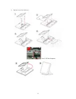
Page 5: ...tem you need to open the system first and the procedure of opening the system is as below 2 Replace the Hard Drive 1 Slide out the back cover 2 Remove the screw and pull out the hard drive 3 Release t...

Page 6: ...ert the hard drive tray into the system hard drive slot 5 Fix the hard drive with screw on the system Security Screws These are security screws and a screw driver for replacing the hard drive Customer...

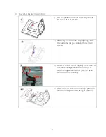
Page 7: ...customer display hinge into the customer display slot and fasten two screws 3 Connect the customer display into COM3 via the cable management slot and adjust COM3 voltage 12V in BIOS refer to Serial P...

Page 8: ...to control the Cash Drawer Register Location A22h Attribute Read Write Size 8bit Bit 0 Cash Drawer DIN bit0 pin input status 1 the Cash Drawer closed or no Cash Drawer 0 the Cash Drawer opened Bit 1 R...

Page 9: ...Windows98 Command Cash Drawer O A22 10 Opening O A22 00 Allow to close Set the I O address A22h bit2 1 for opening Cash Drawer by DOUT bit0 pin controls Set the I O address A22h bit2 0 for allow close...

Page 10: ...nstallation 1 Open the right side cover of system MSR connection is supported on the right side 2 Connect MSR and System connector system connector supports PS 2 interface 3 Fasten the MSR screw on sy...

Page 11: ...6 Metal Stand Installation 11...

Page 12: ...ni Din 4P for Power Input Port DC2 Internal Power Input Connector CD1 RJ11 for Cash Drawer Port LAN1 RJ45 for LAN Port USB1 2 USB dual stack for USB Port USB4 5 6 7 USB Connector COM1 D SUB 9 Pin for...

Page 13: ...MIC1 MIC in Connector LPT1 Printer Connector TOUCH1 5W Resistive Touch Connector PCIE1 Mini PCI E Socket PW1 Power Button Connector IVT1 Inverter Connector FAN1 CPU Fan Connector FAN2 System Fan Conn...

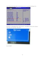
Page 14: ...en the BIOS Main Menu is displayed the following items can be selected Use the arrow keys to select items and the enter key to accept and enter the sub menu Enter System Overview Advanced Settings Use...

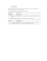
Page 15: ...r I O Configuration Use this menu for set up super I O configuration Serial Port 1 4 Pin9 Mode Enter into serial port 1 4 Pin9 Mode and set up the options then select the serial port 1 Pin9 mode Save...

Page 16: ...every individual driver and utility that enables you to install the drivers in the Driver CD Please insert the Driver CD into the drive and double click on the index htm to pick up the models You can...

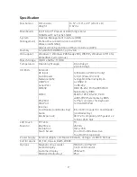
Page 17: ...Port VGA Port Internal Card Reader and Dallas Key Audio Bus Expansion 1 x Mini Din 4P DC 12V only 1 x RJ 11 Power Pin 12V 1 x Gigabit Ethernet by RJ 45 4 x USB 2 0 3 x RS 232 DB 9 RS 232 Pin9 w RI 5V...

Page 18: ...mber has been altered or removed for the product and broken security seal The customer must have model number serial number and original proof of purchase in the form of a bill of sales or receipt inv...

Page 19: ...19 SB 9090 All in One System...

Reviews: