background image

 Appendix 

— 

Technical


Information


13


Note:


For questions about other error messages, please contact the technical support. 

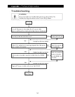
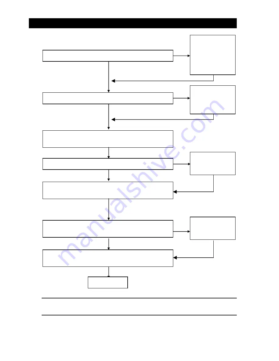
Is


the


LED


on?


Is


the


CPU


fan


running?


Is


there


any


image


on


the


display?


Is


the


keyboard


working?


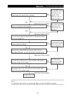
Press


<Del>


to


enter


BIOS


setup


mode.


Select


“Load


Optimized


Defaults”,


save


your


selection,


and


exit


setup.


Turn


off


the


system


and


reboot


after


the


keyboard


and


the


mouse


are


plugged


in.


Reinstall


Windows


OS,


the


add

on


cards,


and


the


cables.


Try


to


reboot


the


system


again.


Turn


off


the


system


and


re

connect


the


IDE


cable.


Reboot


the


system


and


see


if


it


works.


The


problem


may


be


caused


by


power


supply,


CPU,


memory,


CPU,


or


memory


socket.


Failure


has


been


excluded.


The VGA card, VGA 
card slot, or the 
monitor may be 
defective. 

Failure


has


been


excluded.


The keyboard or the 
keyboard connector 
may be defective. 

Failure


has


been


excluded.


The IDE device / 
connector / cable 
may be defective. 

Failure


has


been


excluded.


YES

YES

YES

YES

NO

NO

NO

NO

Problem


solved.

Summary of Contents for SB9100 Series

Page 1: ...SB9100 User Manual...

Page 2: ......

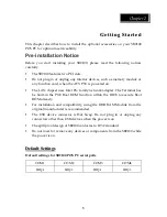
Page 3: ...notices and the User Manual carefully before turning the product on Keep the box and packaging in case the product needs to be shipped in the future Follow the product and warning label instructions...

Page 4: ...eat Do not leave the equipment in a non air conditioned environment where the storage temperature may go above 70 C 158 F as this can cause damage to the equipment M Ma ai in nt te en na an nc ce e Ge...

Page 5: ...ce will not occur in a particular installation If this equipment does cause harmful interference to radio or television reception which can be determined by switching the equipment on and off the user...

Page 6: ...g 4 Chapter 2 4 Getting Started 5 Pre installation Notice 5 Default Settings 5 Limitations 6 Chapter 3 7 System Upgrade 7 Removing the Cover 7 Installing Add On Cards 7 Installing a Hard Disk Drive 8...

Page 7: ...nd c easy maintenance Compact Size Aesthetic Design This sturdy power saving economic POS system features a sleek compact design base that saves counter space and yields a variety of peripheral option...

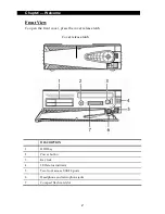
Page 8: ...ew w To open the front cover press the cover release latch DESCRIPTION 1 HDD bay 2 Power button 3 Key lock 4 LED status indicator 5 Two front access USB 2 0 ports 6 Headphone and microphone jacks 7 Co...

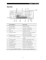
Page 9: ...Type of COM6 6 Microphone Jack Connects to a microphone 7 Audio Line In Out Connectors Connects to audio source external speakers 8 Analog VGA Port Connects to a POS LCD monitor 9 Two USB Ports Conne...

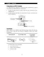
Page 10: ...2 Connect the other end of the VGA cable to the VGA port on the back of the POS LCD Monitor U Un np pa ac ck ki in ng g Before setting up your SB9100 check that the package contains the following ite...

Page 11: ...on The LAN chipset uses Intel Pro family network adapter The Terminal has be built in the PXE Boot ROM function within the BIOS to execute Boot ROM already For installation and compatibility using the...

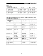
Page 12: ...se the following add on devices to expand the utilities of your SB9100 POS PC Add on Card Type Brand Model No Remarks LAN Realtek RTL8139C D 10 100 Base T SIS SIS900 10 100 Base T D Link DFE 530TX 10...

Page 13: ...erial A container to store the screws temporarily WARNING Make sure that the power of your SB9100 POS PC is turned off before removing the chassis I In ns st ta al ll li in ng g A Ad dd d O On n C Ca...

Page 14: ...POS PC without a hard disk drive contact your dealer for system upgrade M Me em mo or ry y C Co on nf fi ig gu ur ra at ti io on n You can increase the system memory for your SB9100 POS PC via onboar...

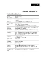
Page 15: ...edia Accelerator 950 On Board Graphic Max Share Memory Up To 224MB Parallel Port One LPT port SPP EPP ECP IRQ and address selectable by BIOS setup Serial Port Total 4 COM ports on board IRQ selectable...

Page 16: ...ontrol System front side tact switch ATX Trigger below the LCD display with bottom Ethernet Port Intel PRO 1000 Ethernet chip on board Intel Ethernet chips on board 10 100 1000 base T Audio AC97 CODEC...

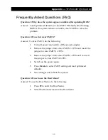
Page 17: ...nswer To clear CMOS do the following 1 Turn off power and switch off the power adapter 2 Remove the jumper from clear CMOS 2 3 PIN and insert the jumper to clear CMOS 1 2 PIN 3 Remove the jumper from...

Page 18: ...ds and cables from motherboard Has the motherboard shorted out Is the memory module correctly installed into the DIMM slot Plug in ATX power cable and turn on the POS PC Next Page Isolate the short pi...

Page 19: ...use are plugged in Reinstall Windows OS the add on cards and the cables Try to reboot the system again Turn off the system and re connect the IDE cable Reboot the system and see if it works The proble...

Reviews: