Logic Digital Controller
User Guide version 3
Page 10 of 31
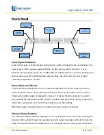
name will indicate the channel pairing. For example ‘A+B’ means both input A and B
parameters. The name of the output will be shown briefly at the top of the display when
stepping onto an output.
Edit Select Buttons
The currently selected edit parameter page is displayed on the bottom left corner of the LCD.
Pressing the edit select buttons moves through the available parameters for the current input or
output.
Text Display
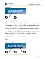
Preset, channel, parameter and status information is shown on the 2x 24-character text display.
In most screens the currently selected channel is displayed on the upper line and the edit
parameter on the lower line. To simplify the display and enhance security, some parameters or
parameter pages are omitted when not relevant.
Parameter Knobs
Three velocity sensitive parameter knobs are used to adjust parameters shown on the display.
Up to three parameters at a time are displayed on the screen. The parameter name is shown
above the parameter value in each of the three screen sections. The parameter knobs have a
fixed association with the screen sections; the rightmost parameter knob adjusts the rightmost
parameter and so on.
Output Signal / Limiter Indication
Two LEDs are provided for each output channel. These show the signal level relative to the
limiter threshold. The yellow LED will light when the signal is 6dB below the threshold and the
red warning LED will light when the limiter threshold is reached.
Mute Buttons and Status LEDs
Each output has a mute button and associated mute status LED. Pressing the button toggles the
mute on and off.
Note that the mute buttons do not function when the secure mode is activated.


