ZOOM OMAP35x DevKit
QuickStart Guide
15
3.
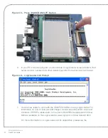
Before using the LCD touch screen, remove the protective plastic film covering the
display.
4.
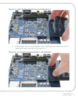
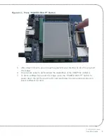
To remove the LCD board from the baseboard, pull back on the ejector levers until
the connector on the display board moves up and disengages from the baseboard
60-pin LCD connector.
2.6 Baseboard Jumper Settings
The following table describes the function of the jumpers on the application baseboard. By
default, most of the jumpers are placed in position for normal operation modes (please refer
to the baseboard connection diagram in Figure 1.2 for jumper locations).
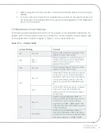
Table 2.10 – Jumper Table
Jumper Settings
Function
JP1
Jmp 2–3
Normal LCD operation
a
. Default is when
jumper is across pins 2 and 3.
JP2
Jmp 1
Jmp 2
Normal operation. An individual jumper is
placed on each pin and not connected to
another pin. (See Figure 2.11 for a
graphical description.)
JP3
Jmp 2–3
ATA Operating Voltage
b
. Default is when
jumper is across pins 2 and 3.
JP4
Jmp 1–2
ATA Disable
. When the jumper is placed
across pins 1 and 2, ATA functionality is
disabled for the board. This is the default
and recommended position of the JP4
jumper for use with the OMAP35x SOM-
LV.
Jmp 1
ATA Enable
. When the jumper is placed
only on pin 1 and not connected to
another pin, ATA functionality is enabled
for the board.
J42
Jmp 1–2
USB 5V control (OMAP35x SOM-LV
acting as USB host). When the jumper is
across pins 1 and 2, the baseboard
supplies 5V to USB1_VBUS signal. This
is the default and recommended position
of the J42 jumper.
No jumper
USB 5V control (OMAP35x SOM-LV
acting as USB device). When the jumper
is removed from J42, the connected USB
host must supply 5V to USB1_VBUS.


