ZOOM OMAP35x DevKit
16
QuickStart Guide
1.
Confirm baseboard ATA jumper (JP4) is set to disable ATA.
2.
Confirm baseboard LCD jumpers (JP1) are set for normal LCD operation.
3.
Confirm baseboard USB 5V control jumper (J42) is set for the OMAP35x SOM-LV
to act as USB host.
4.
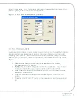
Confirm baseboard JTAG jumpers (JP2) are set for normal operation with the
OMAP35x SOM-LV, as shown in Figure 2.11 below.
Note:
For the OMAP35x SOM-
LV, the jumpers should remain in the same position for both normal and JTAG
operation modes.
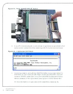
Figure 2.11 – Baseboard JTAG Settings for the OMAP35x SOM-LV
a.
Normal LCD operation is the proper setting for the included 4.3” WQVGA LCD
and for the optional Zoom Display Kits.
b.
ATA is not supported on the OMAP35x SOM-LV.
1
2
6
5
JP2
Normal and JTAG operation


