background image


2. Display 

Modes 


The LNFC display can be in one of three modes: 

current time

edit

, or

 idle

Most of the time the display will be showing the current time. The 

edit


mode is used to change clock and display parameters such as fast rate, 
alarm time, brightness, etc. The 

idle

 mode is entered when the LNFC 

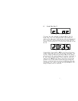
detects that the LocoNet has become idle; the display will look like this: 


ALARM

INIT

TIME

PM


When the LNFC is in the idle mode the current time will be frozen and it 
will not respond to key activity. The LNFC will exit the idle mode when 
the LocoNet is active again. 


3. 

Quick Start Guide 


The LNFC is ready for installation. You should be able to have it up and 
running on the LocoNet in a matter of seconds (

real

 time seconds, not 

fast 

time seconds!). Follow these simple steps: 
 
1.


Plug either end of the enclosed LocoNet cable into either jack on the 
back of the LNFC. Make sure you hear the connector “click.” 

NOTE:


Leave the other end of the LocoNet cable unconnected at this point!  

2.


Insert the small round plug end of the enclosed wall transformer into 
the mating connector on the back of the LNFC. 

3.


Plug the wall transformer into any available AC outlet. 

Caution:


children should not be allowed to do this without adult supervision! 
Electrocution and death could occur!  

4.


The LNFC display should light up and the LNFC should beep twice. 
The display should show “IdLE” as previously illustrated. If this is not 
the case refer to Section 11 on troubleshooting; do not proceed to the 
next step here. 

5.


Plug the remaining end of the enclosed LocoNet cable into any 
available LocoNet jack on your layout. The display will change from 
the idle mode to the current time mode provided the LocoNet is not 
idle. 

Summary of Contents for LocoNet

Page 1: ...HNOLOGIES RAIL TM PMB 287 21175 Tomball Parkway Houston TX 77070 Voice Fax 281 251 5813 email info logicrailtech com http www logicrailtech com LocoNet is a registered trademark of Digitrax Inc 1998 2...

Page 2: ...5 5 Brightness brit 18 5 6 Initial Default Time Init 19 5 7 Code Revision Co X Y 20 5 8 Option Switch oPtn 20 5 9 Reset rSt 23 6 Multiple LNFCs 24 6 1 Establishing the Clock Master 24 6 2 Network Clo...

Page 3: ...12 or 24 hour time format Local alarm 4 independent Event Triggers see section 1 3 Adjustable brightness level Ability to change the network time and fast rate Two LocoNet jacks for connecting to oth...

Page 4: ...that you can configure or select These include Display brightness Hour format 12 or 24 DT100 throttles only support the 24 hour format Local alarm Local alarm behavior on off flashing colon or alarm...

Page 5: ...address but this time the decoder switch is set to the opposite state For example assume the Event Trigger start time is programmed to 6 30pm the end time is programmed to 9 05pm and the switch addres...

Page 6: ...Follow these simple steps 1 Plug either end of the enclosed LocoNet cable into either jack on the back of the LNFC Make sure you hear the connector click NOTE Leave the other end of the LocoNet cable...

Page 7: ...hing time it doesn t make sense to choose a high fast rate if your switching crew is totally overwhelmed by the clock and they can t enjoy their work train speeds the faster you run your trains the fa...

Page 8: ...will decrement the value When entering a time clock initial default alarm or event start end pressing this key will advance the Minutes value When entering an accessory decoder switch address pressin...

Page 9: ...ressing the HRS key the hours will increment from the current setting up to 23 or 11pm and then wrap around to 00 or 12am Change the minutes by pressing the MIN key the minutes will increment from the...

Page 10: ...pressing the MIN key the fast rate will decrement from the current setting down to 00 and then wrap around to A0 If you change your mind and don t wish to change the fast rate simply press the MODE k...

Page 11: ...d to 00 or 12am Change the minutes by pressing the MIN key the minutes will increment from the current setting up to 59 and then wrap around to 00 If you change your mind and don t wish to change the...

Page 12: ...n to off this is how you select whether you want the event trigger to set the switch to closed PM indicator on or thrown PM indicator off NOTE legal DCC accessory decoder addresses must be in the rang...

Page 13: ...ay would look like this The event trigger enables are defined in the following table Each event trigger enable is represented by a single bit and has an associated weight Bit Weight Trigger Definition...

Page 14: ...0 You can decrement the value by pressing the MIN key the value will decrement from the current setting down to 0 and then wrap around to F If you change your mind and don t wish to change the Event T...

Page 15: ...indicates that you are now going to specify the End time for Event 1 You can select a different event number by pressing the HRS or MIN keys Once you have chosen an event number press the SEL key The...

Page 16: ...ed when the PM indicator is not illuminated the switch will be set to thrown When the event end time is reached assuming it s not equal to the start time then the event trigger is sent with the switch...

Page 17: ...will be in effect and stored in non volatile memory as well The display will then show Et S again where is the next event number At this point you can repeat the above procedure for another event trig...

Page 18: ...he brightness setting by pressing either the HRS key or the MIN key If you change your mind and don t wish to change the brightness setting simply press the MODE key the display will return to the cur...

Page 19: ...m and then wrap around to 00 or 12am Change the minutes by pressing the MIN key the minutes will increment from the current setting up to 59 and then wrap around to 00 If you change your mind and don...

Page 20: ...we may ask you for this information Pressing the MODE key will change the display to the current time adjusted for any fast time minutes elapsed while in this editing mode 5 8 Option Switch oPtn ALAR...

Page 21: ...alarm time is reached We recommend that you do not enable this feature and the Alarm Flash Colon 0 Do not flash alarm indicator at alarm time 32 Alarm Disable 1 Disable alarm from sounding or flashin...

Page 22: ...functions that you want to set to 0 simply don t add in their bit weights Now that you have the decimal base 10 value you need to convert it to its hexadecimal base 16 equivalent You should already be...

Page 23: ...n t wish to change the option switch value simply press the MODE key the display will return to the current time adjusted for any fast time minutes elapsed while in this editing mode Once you are sati...

Page 24: ...ock Slave As described in Section 5 7 all LNFCs are enabled as the Clock Master by default factory setting As such you must choose one LNFC as the master and change the option switch setting make sure...

Page 25: ...e two LocoNet jacks on the LNFC board are wired identically As such you can use them interchangeably The LocoNet signals pins 3 and 4 on the two jacks are shorted together this may be useful in some e...

Page 26: ...ur layout or control panel by cutting out a hole that is 4 95 x 2 6 You ll need a depth clearance of 1 5 This is illustrated in the diagram below The fascia plate was designed to allow you to mount th...

Page 27: ...nologies 3 If the current or voltage limitations of the product have been exceeded Requests for warranty service must include a dated proof of purchase a written description of the problem and return...

Page 28: ...e contents of the non volatile storage device on the module are invalid Please contact Logic Rail Technologies directly for assistance 2 The initial default time broadcast from the LNFC doesn t appear...

Reviews: