APPENDIX-B
Installation Manual
Page
20
© Logic Energy Ltd. Registered in Scotland
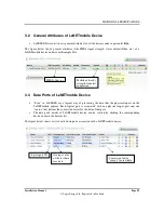
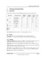
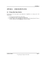
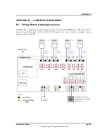
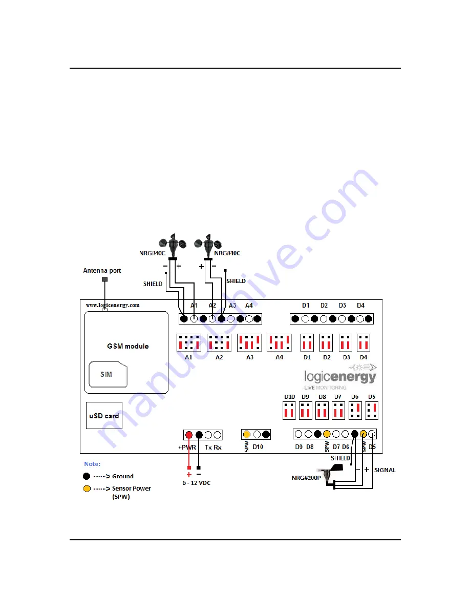
B-3 NRG anemometers and wind vane
This example shows the configuration jumper settings and sensor wiring for a typical wind monitoring
installation using NRG #40C anemometers and NRG #200P wind vane. Note the jumper settings.
Sensors:
•
Port A1 = Primary/top anemometer (NRG #40C)
•
Port A2 = Secondary/lower anemometer (NRG #40C)
•
Port D5 = Primary wind vane (NRG #200P)
Shielded cables must be used for the anemometer and wind vane connections to ensure signal quality.
Connect the shield to GND at the LeNETmobile. Do not connect the shield at the sensor.
Additional anemometers can be connected to ports A3-4, and one additional wind vane can be connected
to port D6. In LeSENSE wind reports, wind vane D6 will be associated with anemometer A2.

