background image


TYPES OF OPERATIONS


Logicube ZClone™Xi User’s Manual 


60 

4.


Type 

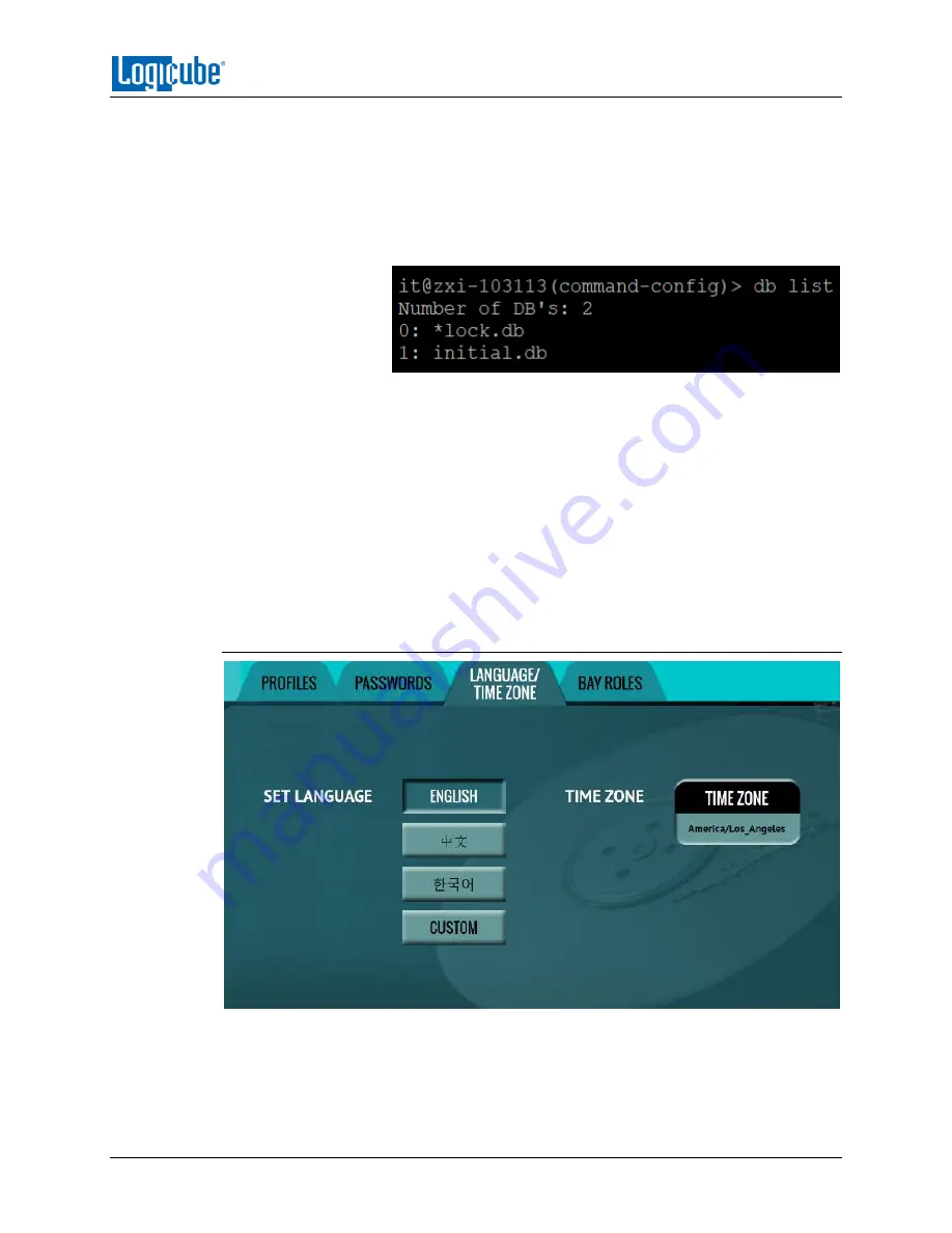
db list

 then press the enter key. This will show a list of 

profiles (or databases) saved. The unit has one default profile 
called 

initial.db

. Any profiles added by users will appear in this 

list.


The example below shows two databases (the default 

initial.db and lock.db). The db that shows an asterisk (*) before 
the name is the current database or profile being loaded each 
time the unit is turned on. 


5.


Type 

db


load initial.db 

then press the Enter key to load the 

default database. There should be a response showing 
“Command (DbManagement) Successful”. 

6.


Type 

db list

 again and there should be an asterisk (*) on 

initial.db. 

7.


Turn the unit off using the power button, then close the 
Telnet/SSH application.  

8.


Turn the unit on. When the unit boots up, it will load the default 
profile (INITIAL.DB). 

5.9.3   Language/Time Zone 


The menu system’s language can be changed. The available languages are English, 
Chinese (

中文

), Korean (

한국어

), and Japanese (

日本語

). 

This screen also allows the time zone to be set.  

Summary of Contents for ZClone Xi

Page 1: ...Logicube ZClone Xi User Manual I ZClone Xi User s Manual Logicube Inc Chatsworth CA 91311 USA Phone 818 700 8488 Fax 818 700 8466 Version 2 0u8a Date 10 19 2018 MAN ZXi ...

Page 2: ...NTY OR ON A TIME AND MATERIALS BASIS Warranty DISCLAIMER IMPORTANT PLEASE READ THE TERMS OF THIS AGREEMENT CAREFULLY BY INSTALLING OR USING LOGICUBE PRODUCTS YOU AGREE TO BE BOUND BY THIS AGREEMENT IN NO EVENT WILL LOGICUBE BE LIABLE WHETHER UNDER THIS AGREEMENT RESULTING FROM THE PERFORMANCE OR USE OF LOGICUBE PRODUCTS OR OTHERWISE FOR ANY AMOUNTS REPRESENTING LOSS OF PROFITS LOSS OR INACCURACY O...

Page 3: ... AN EQUIVALENT OR SUCCESSOR PRODUCT AT LOGICUBE S DISCRETION THIS WARRANTY EXTENDS ONLY TO THE END PURCHASER OF LOGICUBE PRODUCTS THIS WARRANTY DOES NOT APPLY TO AND IS NOT FOR THE BENEFIT OF RESELLERS OR DISTRIBUTORS OF LOGICUBE PRODUCTS UNLESS OTHERWISE AGREED IN WRITING BY LOGICUBE NO WARRANTY IS PROVIDED TO RESELLERS OR DISTRIBUTORS OF LOGICUBE PRODUCTS IN ORDER TO RECEIVE WARRANTY SERVICES CO...

Page 4: ...S DIRECTIVE PROHIBITS THE SALE OF CERTAIN ELECTRONIC EQUIPMENT CONTAINING SOME HAZARDOUS SUBSTANCES SUCH AS MERCURY LEAD CADMIUM HEXAVALENT CHROMIUM AND CERTAIN FLAME RETARDANTS IN THE EUROPEAN UNION THIS DIRECTIVE APPLIES TO ELECTRONIC PRODUCTS PLACED ON THE EU MARKET AFTER JULY 1 2006 Logicube Technical Support Contact Information 1 By website www logicube com 2 By email techsupport logicube com...

Page 5: ... ON AND OFF 6 2 2 CONNECTING VARIOUS DRIVE TYPES 7 2 3 DRIVE BAY LEDS 8 2 4 THE USER INTERFACE 8 2 5 TOUCH SCREEN 9 2 6 HDMI 9 2 7 OPERATING SYSTEM AND ZXI APPLICATION SOFTWARE 9 3 QUICK START 10 3 0 QUICK START GUIDE 10 3 1 DRIVES 10 3 1 1 Blank Disk Check 10 3 2 CLONE 11 3 2 1 Step By Step Instructions Clone 12 3 3 HASH 13 3 3 1 Step By Step Instructions Hash 14 3 4 WIPE FORMAT 14 3 4 1 Step By ...

Page 6: ...ob Info 31 4 3 2 HPA DCO 31 4 3 3 Error Handling 31 4 3 4 Hash Verification Method 32 4 3 5 File Image Method Settings 33 4 3 6 Clone Method Settings 33 4 4 TARGET IMAGE FILE 34 4 4 1 Selecting Target Drives or Images 34 4 5 STARTING THE CLONING OPERATION 35 5 TYPES OF OPERATIONS 37 5 0 TYPES OF OPERATIONS 37 5 1 DRIVES 39 5 2 CLONE 39 5 3 HASH 39 5 3 1 Target 40 5 3 2 Settings 40 5 3 2 1 Hash Set...

Page 7: ...les 62 5 10 NETWORK SETTINGS 62 5 10 1 Services 63 5 10 2 Interfaces 63 5 10 2 1 Configuring a Static IP Address 64 5 10 3 HTTP Proxy 65 5 10 3 1 Server 65 5 10 3 2 Username Password 65 5 11 SOFTWARE UPDATE 65 5 12 POWER OFF 66 6 UPDATING LOADING RE LOADING SOFTWARE 67 6 0 UPDATING LOADING RE LOADING SOFTWARE INTRODUCTION 67 6 1 UPDATING LOADING RE LOADING SOFTWARE INSTRUCTIONS 67 6 1 1 From Netwo...

Page 8: ...APTOP CLONING VERSION INTRODUCTION 77 9 1 REQUIREMENTS 77 9 2 SETUP INSTRUCTIONS 78 9 3 ADDITIONAL NOTES 79 9 3 1 Drives 80 9 3 2 Clone 80 9 3 3 Hash 82 9 3 4 Wipe 82 10 CHANGING THE DEFAULT PASSWORDS 83 10 0 CHANGING THE DEFAULT PASSWORDS INTRODUCTION 83 10 1 CHANGING BOTH THE LOGICUBE AND IT PASSWORDS 83 10 2 CHANGING ONLY THE LOGICUBE PASSWORD 84 10 3 CHANGING ONLY THE IT PASSWORD 85 11 FREQUEN...

Page 9: ... ZXi created image repository The ZXi supports SATA and USB3 and supports SAS drives with an optional software activation package PCIe M 2 SSDs are supported with the optional PCIe Bridge adapter that connects to any of the 3 USB 3 0 ports on the ZXi The laptop cloning version of the ZXi allows users to clone up to six laptops Windows or MAC x86 based or tablets Windows x86 based without removing ...

Page 10: ...8 SAS targets when cloning from a network repository or from an external USB enclosure connected to the ZXi SAS option required to clone to SAS target drives Laptop Cloning Version Customers can purchase a version of the ZXi F ZXI LAPTOP that is shipped with a factory installed feature that provides support for cloning of 6 laptops Windows or MAC x86 based or tablets Windows x86 based and 6 hard d...

Page 11: ...e manage image repositories manage network settings create user profiles save configurations manage drive station assignments Audit trail log report provides detailed information on each completed task Logs can be printed using a web browser and your PC Includes a digital signature for authentication purposes A color touch screen display provides an intuitive and easy to use interface HPA DCO supp...

Page 12: ... mini PCIe cards Requires PCIe adapter kit PCIe adapter kit for M 2 PCIe PCIe and mini PCIe cards 2 5 3 5 IDE to SATA adapter 1 8 IDE to SATA adapter 1 8 IDE ZIF to SATA adapter 1 8 micro SATA adapter mSATA to SATA adapter eSATA 18 cable Flash card reader for compact flash media Extended warranties WARNINGS Avoid dropping the Logicube ZXi or subjecting it to sharp jolts When in use place it on a f...

Page 13: ...ed 2 0 Overview of the ZXi Special Icons Throughout this manual there are two icons that can be seen Please pay close attention when any of these two icons are found These icons highlight additional information or important warnings on specific topics ...

Page 14: ...luded power cable the power connector in the back of the ZXi To turn the ZXi on turn the power switch located next to the power connector in the back of the ZXi to the ON position Press and release the power button on the front of the ZXi The ZXi will turn on and start the boot process It is normal for the fans to either turn off or slow down after the initial start up sequence ...

Page 15: ...he left and select the Options tab If you need to purchase the SAS option contact our sales team at sales logicube com Cables and adapters are available for the following drive types SAS SATA USB 1 8 microSATA optional 2 5 and 3 5 PATA IDE optional 1 8 ZIF optional 1 8 PATA IDE optional eSATA optional mSATA optional Flash Media optional When drive adapters are being used it is recommended to keep ...

Page 16: ...e s information is being accessed This is typically blinking when a drive is connected while the ZXi is gathering drive information details or during any clone wipe or hash task as the ZXi is either reading from the drive or writing to it ON Solid This LED will turn solid if a drive that is being cloned to hashed or wiped stops working alerting that there may be a problem with the drive 2 4 The Us...

Page 17: ...d in the back panel Simply connect an HDMI cable from the ZXi to an external display that supports HDMI and the ZXi will automatically show the display on both the ZXi and the external display To change the display resolution on the external display 1 Connect a wired USB keyboard to one of the back USB 2 0 host ports 2 Press ALT R An on screen display should appear on the external display that all...

Page 18: ...ge of the drive manufactured date How often that drive has been used For example a 2 TB drive with 64MB of cache produced by the manufacturer 2 years ago is most likely slower than a 2 TB drive that the same manufacturer just released this year even though they are both 7200RPM with 64MB of cache and are both SATA III 3 1 Drives This screen shows the status of all drive bays Each drive bay will be...

Page 19: ...Drives can be cloned using Mirror bit for bit copy or Clever copies only data areas skips blank sectors and partitions can be resized to fit larger capacity drives These selections should be performed in order from left to right Details on the different screens found in the Imaging operation can be found in Chapter 4 Cloning For details on cloning drives to a smaller capacity Target see Section 4 ...

Page 20: ...used For example a 2 TB drive with 64MB of cache produced by the manufacturer 2 years ago is most likely slower than a 2 TB drive that the same manufacturer just released this year even though they are both 7200RPM with 64MB of cache and are both SATA III 3 2 1 Step By Step Instructions Clone 1 Select Clone from the types of operation on the left side 2 Tap Mode and select Drive to Drive Image to ...

Page 21: ...PLETED At this point it is recommended to tap Reset Task to reset the task so the drive bays properly reset and not show as being used or assigned for other tasks The number of bytes shown on the progress bar is not the actual size of the drive This is the actual bytes being processed When Verify is set to Yes the reported number will double in size 3 3 Hash A hash or operation can be performed to...

Page 22: ...o start the hash task 7 When finished the status will show COMPLETED At this point it is recommended to tap Reset Task to reset the task so the drive bays properly reset and not show as being used or assigned for other tasks 3 4 Wipe Format Drives connected to bays that are configured as Target or both Master and Target can be wiped or formatted Unless formatted with the ZXi when a drive is wiped ...

Page 23: ...hen Format depending on which methods are chosen For example if both Secure Erase and Wipe Patterns are selected the unit will perform a Secure Erase first then a Wipe Patterns wipe 3 4 1 Step By Step Instructions Wipe Format 1 Select Wipe from the types of operation on the left side 2 Tap the Target icon and select one or more drives then tap the OK icon It is recommended to use the same capacity...

Page 24: ... first if selected then a Wipe Pattern if selected then finally a Format if selected 9 When finished the status will show COMPLETED At this point it is recommended to tap Reset Task to reset the task so the drive bays properly reset and not show as being used or assigned for other tasks 3 5 Task Macros This operation allows up to five 5 macros that can be set Each macro can run up to nine 9 tasks ...

Page 25: ...e and clone tasks Once the wipe for example Wipe 1 and clone for example Image 1 has been set up the Task Macro can be set 3 5 1 Step By Step Instructions Task Macro Tapping this icon allows the user to set specific tasks for each macro The following window will appear Tap Operation 1 to set the first operation in the macro The following screen will appear allowing the user to choose the task Tap ...

Page 26: ... the task list tap the Start icon in the Task Macro screen Example Setting up a Macro for a Wipe to Secure Erase then perform a Drive to Drive Clone To set a macro to perform a Wipe using Secure Erase on T1 immediately followed by performing a Drive to Drive Clone from M1 to the newly wiped secure erased drive on T1 the Wipe and Clone Tasks first need to be set up 1 First set the Wipe task Select ...

Page 27: ...ations on the left side 4 Tap the Tasks icon to select the different tasks for the macro 5 Tap the field next to Operation 1 to set the first operation Since the first task to be run is the Wipe task select Wipe 1 then tap OK 6 Tap the field next to Operation 2 to set the second operation Since the second task to be run is the Drive to Drive Clone task select Clone 1 then tap OK 7 The screen shoul...

Page 28: ...tored and saved on the unit Logs can be viewed directly on the unit or from a computer s browser if the unit is connected to a network In addition to viewing the logs can be exported to an external USB location such as a USB flash drive Logs are exported in PDF HTML and XML format Details for the Logs screen can be found in Section 5 6 Logs 3 6 1 Step By Step Instructions Viewing or Exporting Logs...

Page 29: ...ed they can be exported in a single operation Log files can also be accessed over the network See Section 3 6 3 for details To print the log files it is recommended to use the web interface as described in Chapter 7 Remote Operation and click the print icon on the upper right corner of the screen The browser s print menu will appear and the log can be printed to an available printer on configured ...

Page 30: ... the Statistics screen See Section 5 7 for more information on the Statistics screen 2 A Windows security screen will appear prompting to enter a User name and Password to connect to the unit Login with the following credentials User name it Password it 3 Once connected an auditlog folder will appear Open the auditlog folder 4 The auditlog folder contains the HTML PDF and XML files for each of the...

Page 31: ...Displays a diagram of the input and output ports located in the back of the unit Options Displays which optional software is available and what is installed Network Interface Stats Displays the Network Interface statistics Receive and Transfer bytes packets drops and errors and the link status 3 8 Manage Repositories Repositories can be added to the unit in this operation Repositories can be drive...

Page 32: ...rk interface which include setting a static IP address and allows certain network services to be enabled or disabled HTTP Proxy For the unit to be able to update software from a network over the internet proxy settings may need to be set Networks that have a proxy server for internet access will require proxy settings for devices like this to connect to the Internet This typically includes a serve...

Page 33: ...e different Network Settings screens can be found in Section 5 13 Power Off POWER OFF The unit can be remotely turned off or restarted by going to this tab Additionally the unit s screen can be refreshed DRIVE POWER Inactive drives connected to the unit can be set to go to standby mode in this tab The default is set to 0 minutes OFF ...

Page 34: ... same number of sectors or Logical Block Addresses LBAs or a larger number of sectors or LBAs than the Master If the Master drive is larger in capacity than any Target drive it is still possible to clone the drive but there are some adjustments that will need to be made to the Master drive The following applies to any Operating System The total partition sizes on the Master drive need to be adjust...

Page 35: ...can be cloned using any of the cloning methods Depending on the Operating System and cloning method used there may be limitations to cloning the drive 4 0 2 BIOS UEFI Partitioning Schemes and Sector Sizes The ZXi supports the following BIOS UEFI Drives that come from devices that use BIOS or UEFI are supported MBR GPT Both partitioning schemes are supported 512 4096 4K Sector Size Drives Drives wi...

Page 36: ...ns when using the Clever Copy method For Windows all System Restore Recovery and OEM partitions should not be expanded The Target drives should be the same capacity or larger If the Target drive is smaller in capacity please see Section 4 0 1 4 0 5 Cloning BitLocker Encrypted Drives Drives that are encrypted with BitLocker can be cloned BitLocker only encrypts partitions not the entire drive Depen...

Page 37: ...e to Drive Restores a ZXi created image file to one or more drives Drive to Image Creates an image file from the Master drive The image file can be written to a drive or a network repository 4 2 Master Image File When Drive to Drive or Drive to Image mode is selected the Master window will show all drives connected to the bays or ports configured as Master or both Master and Target ...

Page 38: ...tings Depending on the selected mode different screens will appear Job Info Available in all modes See Section 4 3 1 HPA DCO Available in the following modes See Section 4 3 2 Drive to Drive Drive to Image Error Handling Available in all modes See Section 4 3 3 Hash Verification Method Available in all modes See Section 4 3 4 Hash Method is not available in Image to Drive File Image Method Setting...

Page 39: ... z Underscore _ Numbers 0 to 9 Hyphen Dash 4 3 2 HPA DCO HPA DCO is available in the following modes Drive to Drive and Drive to Image An HPA or DCO configuration on a hard drive is designed to change drive characteristics such as drive capacity speed and other settings as they are reported to the computer s BIOS The HPA DCO setting allows the user to set whether a drive s HPA or DCO is to be unlo...

Page 40: ...rive but is not selectable The unit will automatically use the hash method that was selected when the image was created using Drive to Image Hash Will hash the Master drive with the selected method There different hash algorithm options available depending on which Imaging mode is selected None No hash of the Master will be performed This is available only when using the following mode o Drive to ...

Page 41: ...ks from the start of the Target By default this is set to 0 or the beginning of the Target The specific number of blocks can be set for each of the options by tapping the edit icon This screen also displays an option to select whether the Master drive is a part of a RAID configuration or a NON RAID configuration When cloning from drives from a RAID configuration the Target drives may need to be in...

Page 42: ...ive or Image to Drive was chosen as the mode the following screen will appear This will allow the selection of one or more Targets It will display all available drives that are connected and set as a Target or Both Master Target The More Info icon displays more information on the drive The drive details window will appear showing information about the drive If DRIVE TO IMAGE was chosen as the mode...

Page 43: ...ge When selected a screen will appear showing details on the selected image file 4 5 Starting the Cloning Operation Once all the settings and options have been selected or set tap the Start icon to begin the Cloning operation A confirmation screen will appear Tap the Yes icon to continue A progress bar will appear at the bottom of the screen showing the bytes processed the rate speed elapsed time ...

Page 44: ...e Xi User s Manual 36 When finished the status will show COMPLETED At this point it is recommended to tap Reset Task to reset the task so the drive bays properly reset and not show as being used or assigned for other tasks ...

Page 45: ...nected 2 CLONE There are three cloning modes available Drives can be cloned using Mirror bit for bit copy or Clever copies only data areas skips blank sectors and partitions can be resized a Drive to Drive Performs a bit for bit copy of the Master producing an exact duplicate of the Master drive b Image to Drive Restores an image created by the ZXi to one or more Target drives c Drive to Image Cre...

Page 46: ...that include About This screen will show information about the unit including the current software installed Adv Drive Statistics Displays S M A R T information taken directly from what the drive is reporting I O Ports Displays a diagram of the input and output ports located in the back of the unit Options Displays which optional software is available and what is installed Network Interface Stats ...

Page 47: ... can be restarted or turned off on this screen This can be useful when using the web interface The User Interface can also be refreshed in this screen Drive Power Drives can be powered down automatically when not in use 5 1 Drives This screen shows the status of all drive bays Each drive bay will be listed whether there is a drive connected or not If there is a drive connected the model of the dri...

Page 48: ...anual 40 5 3 1 Target Tap this icon to select which drive s will be hashed The unit will show all connected Master and Target drives Tap the drive s to be hashed then tap OK 5 3 2 Settings Tap this icon to choose a drive to adjust the hash settings ...

Page 49: ...he expected hash value instructs the unit to hash the drive then verify the hash with the expected value set Each hash task is Logical Block Address LBA based and will hash drives based on the number of LBAs If multiple drives are selected to be hashed the unit will hash up to the LBA value of the smallest capacity drive 5 3 2 1 1 Hash Method Select one of the following hash methods SHA 1 SHA 256 ...

Page 50: ...reen keyboard will appear and the expected hash value can be set There is a Clear All button to easily clear all values 5 3 2 1 3 LBA The LBA icon will bring up the LBA settings screen The user can adjust the percentage or the number of blocks of the drive to hash and where to start the hash By default the length is set to 100 whole drive and the starting percentage is set to 0 start of the drive ...

Page 51: ... to set a specific pattern to use for wiping the drive The number of passes is customizable up to 7 passes along with the type of data written for each pass In addition a 7 pass DoD wipe can be set with pre selected pass values Format Formats the Target drive with one of the following user selectable file systems with or without encryption EXT4 or NTFS The following selections are available when p...

Page 52: ...he drive 5 4 2 1 Secure Erase Choose ON to Secure Erase the selected Target drive s Most drives support this function Secure Erase will send a command to the drive instructing it to reset itself to the specifications the drive manufacturer has set Secure erase will not work on drives connected through the USB ports For SAS Serial Attached SCSI drives Secure Erase sends a Format command For SATA Se...

Page 53: ...ame capacity drives per task When smaller capacity drives are wiped together with larger capacity drives the smaller drives will finish first However the ports will not be available until the entire task is finished 5 4 2 2 1 Mode Selecting Mode will open the Wipe Mode screen showing the following options NONE Choosing this will instruct the unit not to perform a wipe using Wipe Mode DOD Choosing ...

Page 54: ...will change depending on the Wipe Pattern Mode selected If None was selected this is not selectable If DoD was selected all 7 passes will be pre filled Users can edit the pass values by tapping the edit icon The default values are 00 01 00 FF F6 00 XX random If Custom was selected one pass will be pre filled with a random value Users can edit the pass values if desired by tapping the edit icon The...

Page 55: ...or NTFS file system These settings are available Format When set to ON the Target drive will be formatted The drive will be formatted with the user s choice of file system EXT4 or NTFS When set to OFF the Target drive will not be formatted File System Select the file system to be used to format the Target drive Users can select EXT4 or NTFS 5 4 3 Job Info The Job Info setting allows users to enter...

Page 56: ...sks for each macro Tap Operation 1 to set the first operation in the macro The following screen will appear allowing the user to choose the task Tap the OK icon to continue Example Setting up a Macro for a Wipe using Secure Erase then perform a Drive to Drive Clone To set a macro to perform a Wipe using Secure Erase on T1 immediately followed by performing a Drive to Drive Clone from M1 to the new...

Page 57: ... are kept from all imaging hash and wipe operations Logs can be viewed directly on the unit or from a computer s browser if connected to a network For wipe operations logs are kept if secure erase or wipe patterns is selected If the drive is just formatted without secure erase or wipe patterns no log will be created In addition to viewing the logs can be exported to an external USB location such a...

Page 58: ...atistics I O Ports Options and Network Interface Stats 5 7 1 About Screen The About screen will show information about the unit including the current software installed 5 7 2 Adv Drive Statistics The Adv Drive Statistics tab shows S M A R T Self Monitoring Analysis and Reporting Technology information taken directly from what the drive is reporting Navigate between drives by using the left and rig...

Page 59: ... located in the back of the ZXi 5 7 4 Options The Options tab displays available software options and which options are installed on the unit To purchase an option please contact Logicube Sales sales logicube com If an option has been purchased but is not showing as installed please contact Logicube Technical Support support logicube com ...

Page 60: ...screen displays the Network Interface statistics Receive and Transfer bytes packets drops errors and the link status 5 8 Manage Repositories Networked repositories can be added using this operation When Manage Repositories is selected the following tabs are available at the top of the screen ...

Page 61: ...rator to ensure proper configuration for sharing 5 8 1 Add Remove A list of repositories will be shown The user has the option of adding or deleting a repository This will include all drives attached to bays that are set to Target or Master Target and any networked repository If a repository location shows NOT MOUNTED it is because the drive attached is not formatted by the unit or the unit cannot...

Page 62: ...y Tap the OK icon when finished Tap Drive to select network share to set as a repository Tap the OK icon when finished Tap Network Settings to enter the network settings See the example below Tap the OK icon when finished For the Path make sure the forward slash is used and not the backslash symbol ...

Page 63: ...ff the changes must be saved and loaded to a profile Details on profiles can be found in Section 5 9 1 5 8 2 iSCSI This screen allows a user to add a repository using the iSCSI protocol To add a repository using the iSCSI protocol an iSCSI Target must be setup on the remote system Since networks are configured differently a Systems Administrator or Network Administrator may be needed to set up the...

Page 64: ...s This screen shows all user profiles The following selections are available in this screen New Allows the user to create a new profile name Save Saves the selected profile Load Loads the selected profile The unit will boot with the profile that has an asterisk next to the name The Profiles tab allows users to create save and load different profiles with different configurations When a profile is ...

Page 65: ...the profile 7 Make sure the profile to be loaded during the boot process is highlighted for example ImageToDrive DB and tap the Load icon A confirmation screen will appear 8 The next time the unit is turned on it will load ImageToDrive profile To delete a profile highlight the profile to be deleted then tap the delete icon A confirmation screen will appear Tap the Yes icon to delete the selected p...

Page 66: ...og File Deletion Local HTTP Remote HTTP and Config Lock can be saved into a user profile and loaded each time the unit is turned on See Section 5 9 1 for more information on saving and loading a user profile Remember the Config Lock Key If the unit is configured to load a user profile with the Config Lock set enabled and the password is forgotten the only way to reset the Config Lock is load the I...

Page 67: ...unlock key Network Settings This entire section cannot be accessed without the Config Lock unlock key Software Updates This entire section cannot be accessed without the Config Lock unlock key Power Off This entire section cannot be accessed without the Config Lock unlock key The unit can still be turned off without the unlock key by using the power button located on the front of the unit 5 9 2 2 ...

Page 68: ...ng loaded each time the unit is turned on 5 Type db load initial db then press the Enter key to load the default database There should be a response showing Command DbManagement Successful 6 Type db list again and there should be an asterisk on initial db 7 Turn the unit off using the power button then close the Telnet SSH application 8 Turn the unit on When the unit boots up it will load the defa...

Page 69: ...tton is reserved for future language releases 5 9 3 2 Time Zone The unit utilizes NTP Network Time Protocol Each time it is connected to a network with internet access it will automatically check for the correct time using NTP and adjust the time as needed The unit also has a time zone setting Tap Time Zone to select the time zone region Tap the OK icon to continue After selecting the region selec...

Page 70: ...hat profile then reboot See Section 5 9 1 for more information on saving and loading a profile 5 10 Network Settings The Network settings screen has the following tabs Services Interfaces and HTTP Proxy The Services tab allows certain services to be enabled or disabled The Interfaces tab allows the configuration of the network interface which include setting a static IP DHCP is set by default and ...

Page 71: ...f traffic a network tool to measure bandwidth performance Ping Disabling this will block ping access to the unit Disabling any of the services above will disallow the types of communication controlled by those services For example if HTTP is disabled users will not be able to see the unit through a web browser over the network Please contact your Network or Systems Administrator before changing an...

Page 72: ... a static IP address The steps below outline how to configure the unit with a static IP address 1 From the Network Interface Configuration screen above tap the Type box and select STATIC then tap the OK icon The IP SETTINGS box should now be selectable 2 Tap the IP SETTINGS box to manually set the IP address NetMask Gateway and DNS Server When finished tap the OK icon ...

Page 73: ...n to set the IP address or server name and port of the proxy server 5 10 3 2 Username Password If the proxy server requires a username and password for authentication tap the Username Password icon to set this information 5 11 Software Update New and improved software will be released from time to time There are two ways to update the software From the web through a network connection or from a US...

Page 74: ...lable in the Power Off screen POWER OFF The unit can be remotely restarted or turned off by going to this tab Additionally the Graphical User Interface GUI can be refreshed DRIVE POWER Connected inactive drives can be set to go to standby mode in this tab The default is set to 0 minutes Off Disabled ...

Page 75: ...p to date instructions on updating the software can be found on the ZXi s support page 6 1 1 From Network Over the Internet The software can be updated re installed by connecting the unit to a network with internet access 1 Connect the unit to a network with internet access and turn the unit on 2 From the main menu locate and tap the Software Updates icon on the left side 3 Select From Network The...

Page 76: ...en appears connect the USB flash drive that has the extracted software from step 2 to the U1 port the front USB port 4 From the main menu on the unit locate and tap the Software Updates icon on the left side 5 Select From USB Drive The unit then check for the version of the software on the USB drive After a few seconds one of the following messages should appear Software found A software version i...

Page 77: ... A message will appear FIRMWARE UPDATE COULD TAKE UP TO A FEW MINUTES TO COMPLETE PLEASE DO NOT INTERRUPT POWER DURING THIS TIME ON COMPLETION THE UNIT WILL AUTO RESTART AND CONFIRM THE UPDATE Tap the OK icon to start the firmware update process When the OK icon is tapped the screen may appear to do nothing Do not keep tapping the OK icon The firmware update will take no more than 120 seconds When...

Page 78: ...s may not display the Graphical User Interface GUI properly 7 1 Web Interface Using a web browser go to the IP address or the hostname of the unit Both IP address and hostname can be found by going to the Statistics screen For example browse to http 192 168 1 100 or http zxi XXXXXX where XXXXXX is the 6 digit serial number of the unit The web interface will appear on the browser screen All screens...

Page 79: ...ter A login should appear 5 Login with the username it without the quotes and the password it without the quotes A command prompt should appear on the Telnet window The unit can now be configured or managed through the command line interface 7 2 2 Connecting using SSH Connecting using SSH Secure Shell is very similar to connecting using Telnet Since Windows does not have a built in SSH client a th...

Page 80: ...ate a usable computer network based on the Internet Protocol Suite TCP IP For example when the unit is connected connected through a network cable directly to a Windows based computer that is DHCP enabled both the unit and the Windows based computer will automatically configure themselves to be seen by each other using TCP IP with a 169 254 x x IP address configuration ...

Page 81: ...ository stored on an external USB enclosure connected to the ZXi If the SAS option is installed and the Drive Expansions are installed bays T6 and T7 will be able to detect and use SAS drives If the SAS option is not installed and the Drive Expansions are installed bays T6 and T7 will only be able to detect other supported drives except for SAS drives 8 1 1 Attaching the removable ZXi DriveStation...

Page 82: ...is purchased an updated license file will need to be installed re installed along with the ZXi software See Chapter 6 for details on how to load or reload the software 8 4 PCIe Bridge The Logicube PCIe Bridge is a hardware option that provides PCIe drive support on the ZXi The PCIe Bridge can be purchased as a single device or as a kit Part number F ADP PCIE BRG KT which includes the PCIe adapter ...

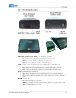
Page 83: ...etween the PCIe Bridge and the ZClone Xi On Detects an active link between the PCIe Bridge and the ZClone Xi Off There is no active link between the PCIe Bridge and the ZClone Xi ALERT HPA and or DCO detection On Detects the presence of an HPA and or DCO on the connected drive Off Does not detect the presence of an HPA and or DCO on the connected drive POWER Power LED On The PCIe Bridge is powered...

Page 84: ...er end of the cable to the PCIe Bridge s host port on the right side 4 Connect the AC adapter power supply to a power source and the PCIe Bridge Logicube has qualified and included a 3 foot USB 3 0 A Male to A Male cable 5 Press and release the power button located on the top of the PCIe Bridge The Power LED will start blinking as the device turns on The boot sequence may take about 30 seconds and...

Page 85: ...le port The ZXi Laptop Cloning Version will be shipped with the following Eight 8 Cat6 Ethernet cables Two 2 Gigabit Ethernet switches with AC adapter power supply Six 6 built in USB cables located in the back of the ZXi 9 1 Requirements Using the ZXi Laptop Cloning Version requires the following Desktops or laptops must be an x86 based Windows or Mac Tablets must have Windows and is x86 based All...

Page 86: ...the Ethernet cable to any port on one of the Gigabit Ethernet Switches E For more than one laptop or computer it is recommended to use both switches to evenly distribute and balance the transfer rate and speed 3 Connect a second Cat6 Ethernet cable D to the other Ethernet port on the ZXi B Connect the other end of the Ethernet cable to any port on the other Gigabit Ethernet switch G 4 For each com...

Page 87: ...ultiple computers Each computer s display monitor will show an IP address for example 169 254 11 21 The ZXi will show the last two segments of the IP address For example I 11 21 The connected drive will show as SDA Additional connected drives will show as SDB SDC etc For example if there are two drives connected to the laptop computer one would show as I 11 21 SDA and the other drive will show as ...

Page 88: ...the drives will show at the bottom of the Drives screen Scroll all the way down to see the connected drives on the tablet laptop computer 9 3 2 Clone The drives will be selectable or grayed out depending on the Mode selected DRIVE TO DRIVE Will show selectable in both the Master and Target screens ...

Page 89: ...VERSION Logicube ZClone Xi User s Manual 81 IMAGE TO DRIVE The drive s will most likely show grayed out un selectable as a Master Repository unless it contains ZXi created images It will be selectable in the Target screen ...

Page 90: ...DRIVE TO IMAGE The drive s will be selectable as a Master As a Repository it may or may not require formatting 9 3 3 Hash All connected drives are selectable in the Hash mode of operation 9 3 4 Wipe All connected drives are selectable in the Hash mode of operation ...

Page 91: ...hen use the following key combinations Alt 2 then Alt Shift Enter 2 Once logicube prompt appears type the following commands one line at a time Press the Enter key after each command line sudo mount o remount rw passwd 3 The following prompt will appear Changing password for logicube current UNIX password 4 Type the current password for the logicube account the default password for this account is...

Page 92: ...d updated successfully 15 Next type the following command sudo smbpasswd it 16 The following prompt will appear New SMB password 17 Type the same password you used in step 5 above The following prompt will appear Retype new SMB password 18 Type the same password again then press the Enter key The Logicube prompt should appear 19 Type the following command then press the Enter key sudo mount o remo...

Page 93: ...ssword 10 Type the same password again then press the Enter key The Logicube prompt should appear 11 Type the following command then press the Enter key sudo mount o remount ro 12 Press the following key combinations to go back to the Graphical User Interface Alt 1 10 3 Changing Only the it Password For the username it 1 Connect a USB keyboard to any available USB port of the ZXi then use the foll...

Page 94: ...Type the same password you used in step 5 above The following prompt will appear Retype new SMB password 9 Type the same password again then press the Enter key The Logicube prompt should appear 10 Type the following command then press the Enter key sudo mount o remount ro 11 Press the following key combinations to go back to the Graphical User Interface Alt 1 ...

Page 95: ... system A Linux based operating system provides increased stability and security over Windows based systems Q Does imaging performance slow down when multiple drives are imaged at the same time A Performance is limited by the slowest drive in the configuration however there should not be any significant speed penalty when imaging multiple drives Q How many separate tasks can you have running concu...

Page 96: ...r will an additional power source be required A Each of the ZXi s USB ports meets the standard specification of up to 5V of power If your USB device has higher power requirements an external power source will be necessary Check with the manufacturer of your USB device to determine the exact power requirements Q Can the ZXi image to an external storage device such as a NAS Network Attached Storage ...

Page 97: ...Laptop Cloning 77 Logs 20 Manage Repositories Network 52 Master 29 Mirror Settings 33 Mode Imaging Mode 29 network connection 70 Overview 5 Passwords 57 83 Profiles 56 Proxy Settings 65 Quick Start 10 Remote Operation 70 73 Remote operation CLI 70 Remote Operation Web Interface 70 RoHS Directive 2002 95 EC III S M A R T Self Monitoring Analysis and Reporting Technology 50 Screen Touch 9 Secure Era...

Page 98: ...i modified monitorix 3 2 1 GPL v2 http www monitorix org modified Electrostatic Discharge ESD WARNING All electronic products may be susceptible to Electrostatic Discharge ESD Electrostatic discharge ESD is the sudden flow of electricity between two electrically charged objects caused by contact an electrical short or dielectric breakdown The ZClone ZXi ZXi has been designed to minimize the effect...

Reviews: