33
GB
32
GB
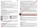
Programming the personalised radio code
Place the coding template positioning pins in the corresponding holes (
Fig. E
).
Hold the template and put the point of the coding tool in the first open hole of
the template.
Press on the coding tool while turning it clockwise to break the corresponding
coding connection. Stop when the handle of the coding tool reaches the coding
template.
Repeat this procedure for each hole in the template.
Remove the coding template, making sure the cut pieces fall outside the detec-
tor. Check that the coding connections corresponding to the personalised radio
code have been properly cut. (Picture
➀
: connection intact ; Picture
➁
: connec-
tion cut).
❑
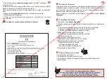
Connect the battery (
Fig. F
).
❑
Test the radio code on the audio sonic detector.
❑
Briefly press the audio sonic detector “Test” button.
The control panel will respond with a voice message or an audible acknowledge-
ment and an indicator light will come on.
If the control panel does not respond, reprogramme the radio code on the detector.
Allocating the detector to a group
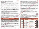
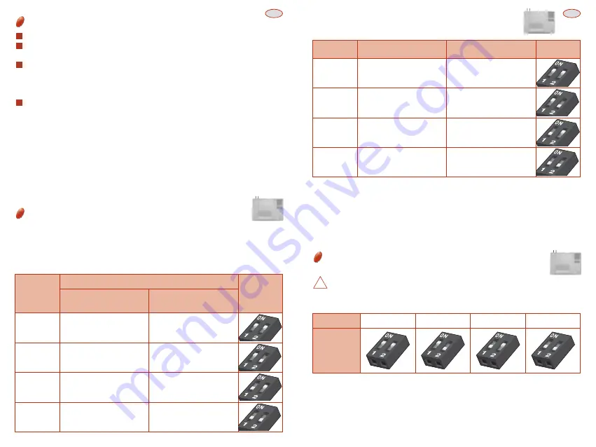
The 2 micro-switches under the cover are for allocating the detector to a
group (
Fig. G
).
Choice of group for detectors linked to a control panel without
point of entry monitoring (other than the L3310 control panel ).
❑
Table 1 (see. type of control panel )
4
3
2
1
Active when Part Set and Fully
Set
Immediate alert
Active when Groups 1 Set
Immediate alert
Group 1
immediate
Group
Detector function
Micro switch
position
control panel in
Part Set/Fully Set mode
control panel in
Group 1 /Group 2 mode
Active when Part Set and Fully
Set Immediate or delayed alert
Active when Groups 1 Set
Immediate or delayed alert
Group 1
delayed
Active when Fully Set
Inactive when part set
Immediate alert
Active when Group 2 Set
Immediate alert
Group 2
immediate
Active when Fully Set
Inactive when part set
Immediate or delayed alert
Active when Group 2 Set
Immediate or delayed alert
Group 2
delayed
Control panels
without
point of entry
monitoring
❑
Table 2 (see. type of control panel )
Active when Part Set
and Fully Set.
Immediate alert
Active when Groups 1 + 2 Set.
Immediate alert
Group 1
Group
Code
control panel in
Part Set/Fully Set mode
control panel in
Independent Groups mode
Active when Part Set
and Fully Set
Set Immediate or delayed alert
Active when Groups 1 + 2 Set.
Immediate or delayed alert
Group 2
Active when Fully Set.
Inactive when part set
Immediate alert
Active when Groups 3 + 4 Set.
Immediate alert
Group 3
Active when Fully Set.
Inactive when part set
Immediate or delayed alert
Active when Groups 3 + 4 Set.
Immediate or delayed alert
Group 4
Control panels
without
point of entry
monitoring
✔
CHECKING THE GROUP ALLOCATION
❑
Briefly press the detector “Test” button (
Fig. G
) and check that the control panel
responds with a voice message or that the indicator light corresponding to the
group selected comes on.
❑
If the control panel does not respond as expected, check the switch positions..
Choosing the identification number
for an audio sonic detector
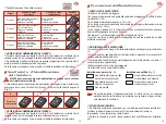
The L3260 must be allocated to a group as a motion detector.
❑
The 2 micro-switches located under the cover allow the selection of one of the
four numbers (
Fig. G
).
✔
CHECKING THE GROUP ALLOCATION
❑
Briefly press the detector “Test” button (
Fig. G
) and check that the control panel
responds with a voice message or that the indicator light corresponding to the
group selected comes on. If the control panel does not respond as expected, check
the switch positions.
!
Number
1
2
3
4
Micro switch
position
Control
panel
L3310
www.absolualarme.com met à la disposition du public, via www.docalarme.com, de la documentation technique dont les références, marques et logos, sont la propriété des détenteurs respectifs


