background image

Logitech Harmony 890 User’s Guide 

                                         Chapter 11: Using the RF Wireless Extender


Draft Sample Layout and Chapter 8 for Logitech,  2-13-08 

 Copyright Reed Consulting Services 

Golden, Colorado      (303) 526-2465


E.


LOCATING THE IR EMITTERS 

  
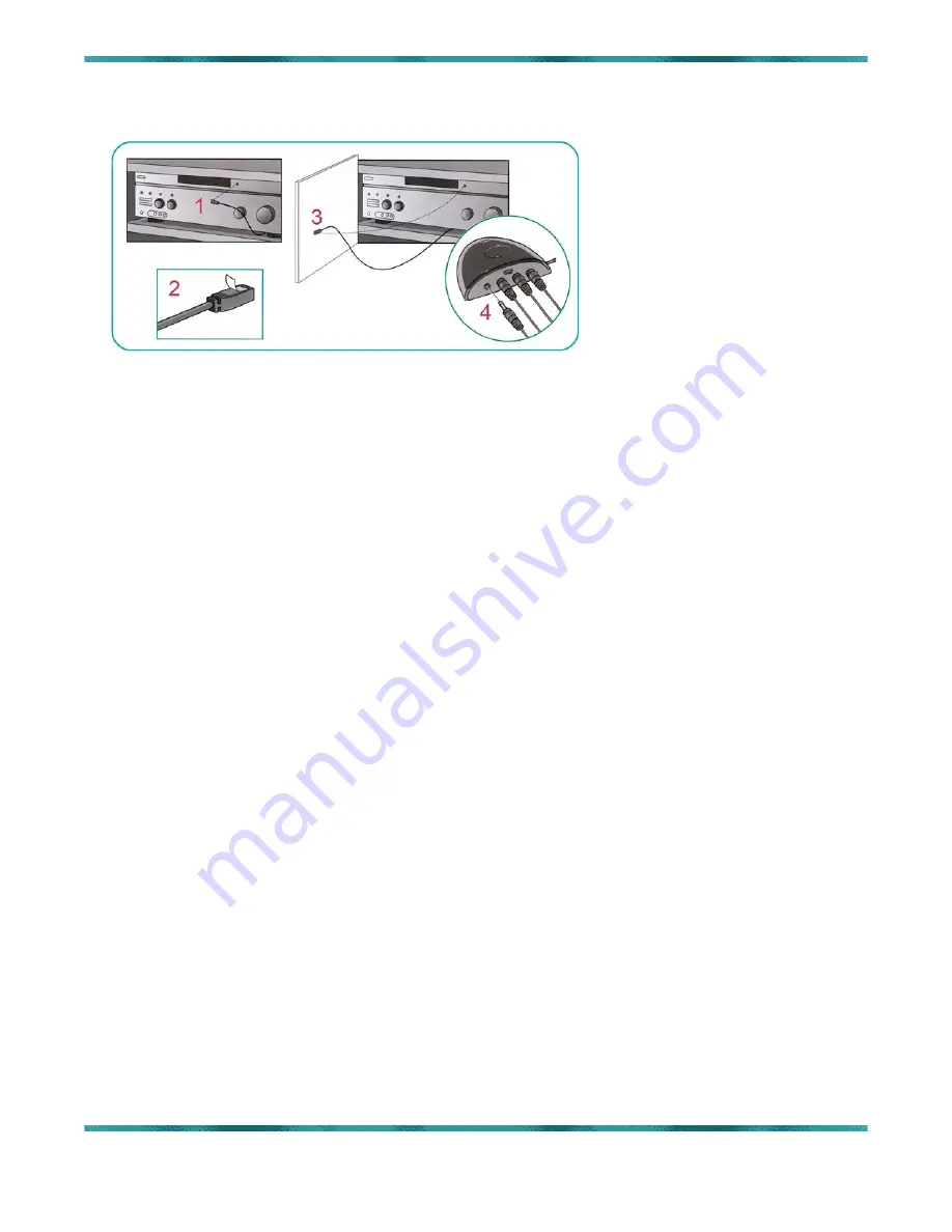
To use the IR emitters, do the following:  


Locate the device’s IR sensor (this is the area (

1

), usually on the front panel of the device, where 

IR signals are received). 


Uncover the adhesive strip (

2

) and attach an emitter directly to this area, or – if you do not want 

to place an emitter directly on the device – attach the emitter on a surface above, below or in 
front of the device, but in a line of sight to the IR sensor. Inside a cabinet, the IR emitter can 

also be attached to a door in front of the device (

3

). 


Each emitter cable has two IR emitters on one end, and can control either one or two devices. If 

only one is needed, leave the other emitter unconnected. Plug the other end of the emitter cable 
into one of the four ports on the Wireless Extender (

4

). 


Your Harmony 890 remote should now control all devices as programmed, whether by IR or RF 

signals. 


Page 18 of 20


Summary of Contents for Harmony 890

Page 1: ...Harmony 890 Advanced Universal Remote User s Guide...

Page 2: ...ER 5 Adding and Managing Devices 7 CHAPTER 6 Adding and Managing Z Wave Devices 8 CHAPTER 7 Creating and Managing Activities 9 CHAPTER 8 Creating and Managing Scenes 10 CHAPTER 9 Customizing the Butto...

Page 3: ...Harmony 890 Minimal instruction but still more than below will be provided directing that user to Charge the 890 s battery Access the Logitech Harmony Remotes website Download the Harmony Remote Softw...

Page 4: ...ated topics will include Capability to control thousands of a v components and home electronic devices by selecting your device from the exhaustive Harmony device database Capability to custom configu...

Page 5: ...e lithium ion battery and charging station with illustrated step by step instructions for Installation removal and replacement of the battery including ordering information Initial and subsequent char...

Page 6: ...rado 303 526 2465 CHAPTER 4 Downloading Software and Firmware This chapter will provide step by step illustrated instructions for the user to Download the latest Harmony Remote software Access the Har...

Page 7: ...or the user to Gather information about component type brand name and model numbers for all a v system devices to be controlled by the Harmony remote a spreadsheet in PDF and Excel versions will be pr...

Page 8: ...y step illustrated instructions for the user to Gather information about Z wave devices to be controlled by the Harmony remote a spreadsheet in PDF and Excel versions will be provided for the user s c...

Page 9: ...ribe what devices will be used and how they are to be set Additional prompting for this data gathering task will include investigating how each device e g TV monitor cycles through or selects inputs A...

Page 10: ...ation of control levels for lighting temperature blinds and other z wave devices with step by step illustrated instructions for the user to Create custom Scenes using the paired Z wave devices added i...

Page 11: ...structions for the user to Create custom button functions by activity for the unused buttons on the remote Create custom override functions for the buttons already programmed Create custom labeled fun...

Page 12: ...Services Golden Colorado 303 526 2465 CHAPTER 10 Creating and Managing Display Themes This chapter will provide step by step instructions for the user to Customize the display background and icons Cre...

Page 13: ...890 remote is to control all your devices by IR If you set the Wireless Extender to control a particular device the 890 sends RF signals to the Wireless Extender which then converts the signals to IR...

Page 14: ...raft Sample Layout and Chapter 8 for Logitech 2 13 08 Copyright Reed Consulting Services Golden Colorado 303 526 2465 B COMPONENTS OF THE WIRELESS RF EXTENDER 1 IR emitter Ports A B C and D 2 USB Port...

Page 15: ...the Wireless Extender Subsequent changes will require that both the Harmony 890 and the Wireless Extender be updated in parallel by connection to your computer via USB and this may require temporary r...

Page 16: ...iple identical devices To do this you will need to assign a specific Port to one or more devices as described below If you are not controlling multiple identical devices skip to Step 5 After selecting...

Page 17: ...m 4 between the Wireless extender and the front face of your A V equipment Plug the AC adapter into an electrical outlet For wall mounting place the Wireless Extender no more than 5 meters 16 feet fro...

Page 18: ...ectly to this area or if you do not want to place an emitter directly on the device attach the emitter on a surface above below or in front of the device but in a line of sight to the IR sensor Inside...

Page 19: ...o significantly reduce the customer frustration and lost profit inherent in high utilization of live support Every user who can successfully program the remote without live assistance is a potential p...

Page 20: ...Logitech Harmony 890 User s Guide Index Draft Sample Layout and Chapter 8 for Logitech 2 13 08 Copyright Reed Consulting Services Golden Colorado 303 526 2465 Index Page 20 of 20...

Reviews: