- 12 -
6
ACCESSORIES
The product comes with a safety valve and a thermometer. Hinges and bolts are mounted onto the heater. It
is in your own interest to check the completeness of the accessories.
With regard to various types of carrying masonry and broad assortment of special anchorage material
available at the market, the manufacturer
does not
provide
heaters with this material. The anchorage
system has to be selected individually, depending on the conditions. We recommend an authorised company
perform mounting on the wall and anchorage, or discuss the anchorage with a professional.
7
WALL MOUNTING
Prior to mounting, check the loading capacity of the wall, If needed, reinforce it. Choose a suitable anchorage
material to suspend the heater, depending on the type of the wall. The water heater shall only be mounted
in vertical position so that the lower edge of the heater is placed at least 60 cm above the floor.
8
PLUMBING FIXTURE
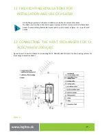
Connection of heaters to plumbing fixtures is illustrated on Figure 6. For potential disconnection of the
heater, the service water inlets and outlets must be provided with screw coupling Js 3/4“. For operation, the
heater must be equipped with a safety valve. The safety valve is mounted on the cold water inlet identified
with a blue ring.
Each hot service water pressure heater must have a safety valve with a membrane spring.
The safety valve must be easily accessible, as close to the heater as possible. The inlet pipes must have at
least the same clearance as the safety valve. The safety valve is placed high enough to secure dripping water
drain by gravity. Safety valves with fixed pressure settings from the manufacturer are used for the assembly.
The start-up pressure of the safety valve must correspond to the max. allowed pressure of the water heater.
If the water main pressure exceeds such value, a reduction valve must be added to the system, whose
working pressure is to be set to 80% of the start-up pressure of the safety valve.
Necessary pressure can be
found in table 2. No stop valves can be put between the heater and the safety valve. During assembly, follow
the guide provided by the safety equipment manufacturer. It is necessary to check the safety valve each time
before putting it into operation. It is checked by manual moving of the membrane from the seat, turning the
make-and-break device button always in the direction of the arrow. After being turned, the button must click
back into a notch. Proper function of the make-and-break device results in water draining through the safety
valve outlet pipe. In common operation, such a check needs to be implemented at least once a month, and
after each heater shutdown for more than 5 days. Water may be dripping off the drain pipe of the safety
valve; the pipe must be open into the air, pointed down; environment temperatures must not drop below
zero.


