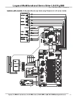
Logosol Multifunctional Servo Drive LS-231g3SB
Doc # 712231005 / Rev. C, 09/13/2018
CONNECTORS
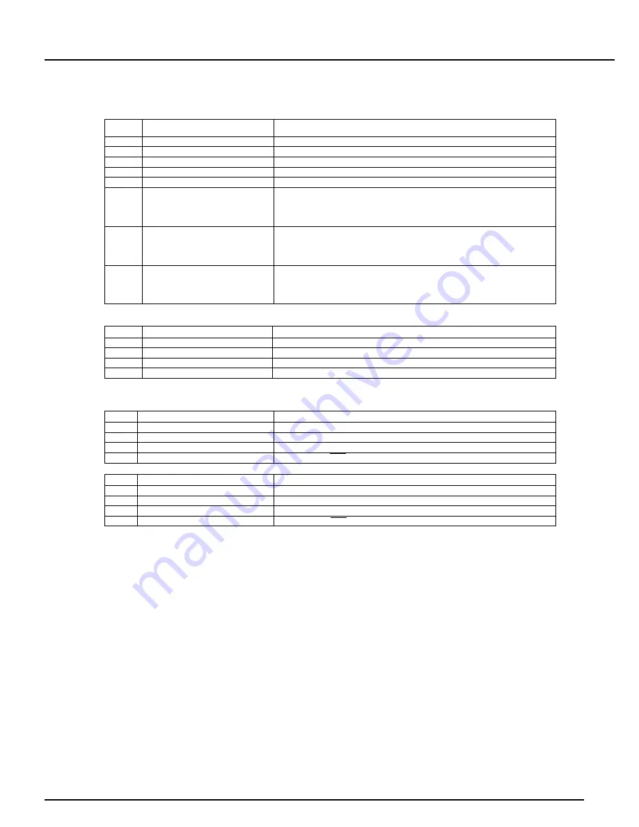
CN1 – POWER AND MOTOR
PIN
SIGNAL
DESCRIPTION
1
+POWER 18Vdc to 180Vdc
Power supply positive terminal
2
+24V 18Vdc to 36Vdc
I/O power supply
3
POWER Gnd
Power supply ground
4
Brake/Output1
Brake output
5
Gnd
I/O ground
6
MOTOR AC3 (W)
Output to motor
Phase 3 terminal for brushless motors
Phase W for Panasonic A and S or MSMD motors
Negative terminal for DC and Voice Coil motors
7
MOTOR AC2 (V)
Output to motor
Phase 2 terminal for brushless motors
Phase V for Panasonic A and S or MSMD motors
Positive terminal for DC and Voice Coil motors
8
MOTOR AC1 (U)
Output to motor
Phase 1 terminal for brushless motors
Phase U for Panasonic A and S or MSMD motors
Not connected for DC and Voice Coil motors
CN2 – I/O
PIN
SIGNAL
DESCRIPTION
1
Gnd
Signal ground
2
Output2
Multifunctional output (mode dependent)
3
Input10
Multifunctional input (mode dependent)
4
Pull-Up
Protected power output (+24V)
SAFETY BUS
CN3
PIN
SIGNAL
DESCRIPTION
1
LIMIT
Limit relay contact (CN3). See note below
2
Input9
Limit input
3
FAULT
Fault relay contact (CN3)
4
Enable
Drive Enable/Stop input
CN4
PIN
SIGNAL
DESCRIPTION
1
LIMIT
Limit relay contact (CN4). See note below
2
Input9
Limit input
3
FAULT
Fault relay contact (CN4)
4
Enable
Drive Enable/Stop input
Note:
SW3=OFF:
-
SW4=OFF – LIMIT relay is open when Limit 1 or Limit 2 is open (CN5pin7 and CN9pin4 or CN5pin15 and CN9pin2), if not bridged.
SW4=ON – LIMIT relay is open when SingleLIMIT is open (CN5pin7 and CN9pin4), if not bridged;
SW3=ON:
-
LIMIT relay is closed only when motor is not moving.
Logosol, Inc.
•
2833 Junction Ave., Ste. 101
•
San Jose, CA 95134
•
Tel: (408) 744-0974
•
www.logosolinc.com
5


