Assembly- and Installation
Instructions
Lohberger Heiztechnik
GmbH
N28/HB N28/GB
Seite 13
Lohberger Heiztechnik GmbH, A-5020 Salzburg-Bergheim, Rechtes Salzachufer 40
Tel. 0662-450444-0, Fax-DW 9
Es gelten unsere aktuellen allgemeinen Geschäftsbedingungen. Irrtum, Druckfehler und technische Änderungen vorbehalten
6.2
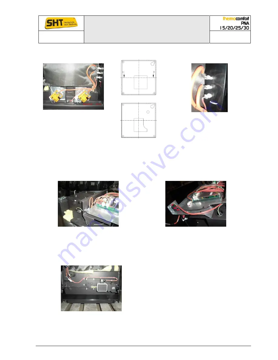
Assembling the primary (PAF) and secondary air flap (SAF) & Ignition
PAF left_ Ignition in the middle_SAF
right
Section PAF
Fittings PAF (8); SAF (9); Ignition (1)
Section SAF
Assemble the PAF & SAF with the supplied allen screws to the three points of the cover. Motor
position as seen in the photo. Then connect the cables to the respective plug. Labeling see pic-
tured above. With new delivery, the ignition element is pre-assembled.
6.3
Assembling FT - Probe
Position FT-probe
Cable bushing FT-probe
The flame temperature probe is placed on the left next to the cleaning lid above. Cables are laid
under the platinum carrier plate and are led back up on the right side through the round cable
entry opening and through the rear cable slot.
6.4
Assembling door contact switch (DCS) and grate-magnet connection
Position DCS & grate-magnet
At the back (rear bottom) of the boiler is the door contact switch (DCS) for the ash pan (2 - pin
connector) or grate-magnet for grate cleaning (plug directly on the grate-magnet).


