Assembly- and Installation
Instructions
Lohberger Heiztechnik
GmbH
N28/HB N28/GB
Seite 28
Lohberger Heiztechnik GmbH, A-5020 Salzburg-Bergheim, Rechtes Salzachufer 40
Tel. 0662-450444-0, Fax-DW 9
Es gelten unsere aktuellen allgemeinen Geschäftsbedingungen. Irrtum, Druckfehler und technische Änderungen vorbehalten
8.8
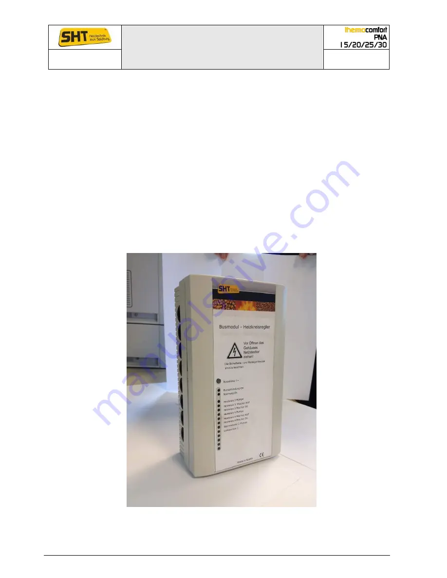
Electrical connecting bus modules heating circuit 3 & 4 or 5 & 6 or solar module
and digital room unit for TC3
The bus module 1 "heating circuit 3 & 4", bus module 2 "heating circuit 5 & 6", bus module 3
"solar module" or digital room unit for HC`s are installed as RS 485 bus modules. Each of these
bus modules has its own bus address.
Examples:
Bus modul 1 „heating circuit 3 &
4
“
Bus modul 2 „heating circuit 5 & 6“
Bus modul 3 „Solar“
Digitale room unit for HC 1
Digitale room unit for HC 2 etc.
A bus address has to be assigned to each of these bus modules.
Cable type bus system:
The design of the connection of the bus modules has to be done with shielded cable with at least
0.5 mm² conductor cross section per wire. To prevent unwanted capacitances between the
conductors a 2x2x0,5mm ² twisted pair - cable (2 twisted pairs and shielding wire) or
3x2x0,5mm²twisted pair should be used, as well as a recommended outer screen of AWG = 20
and, for example, an aluminum-polyester overall screening.
The assembling of the bus module can be selected individually at any point on the wall. The
required screws will be packed together with the controller.


