


3.4
Installation
&
Operation
for TIG
Welding
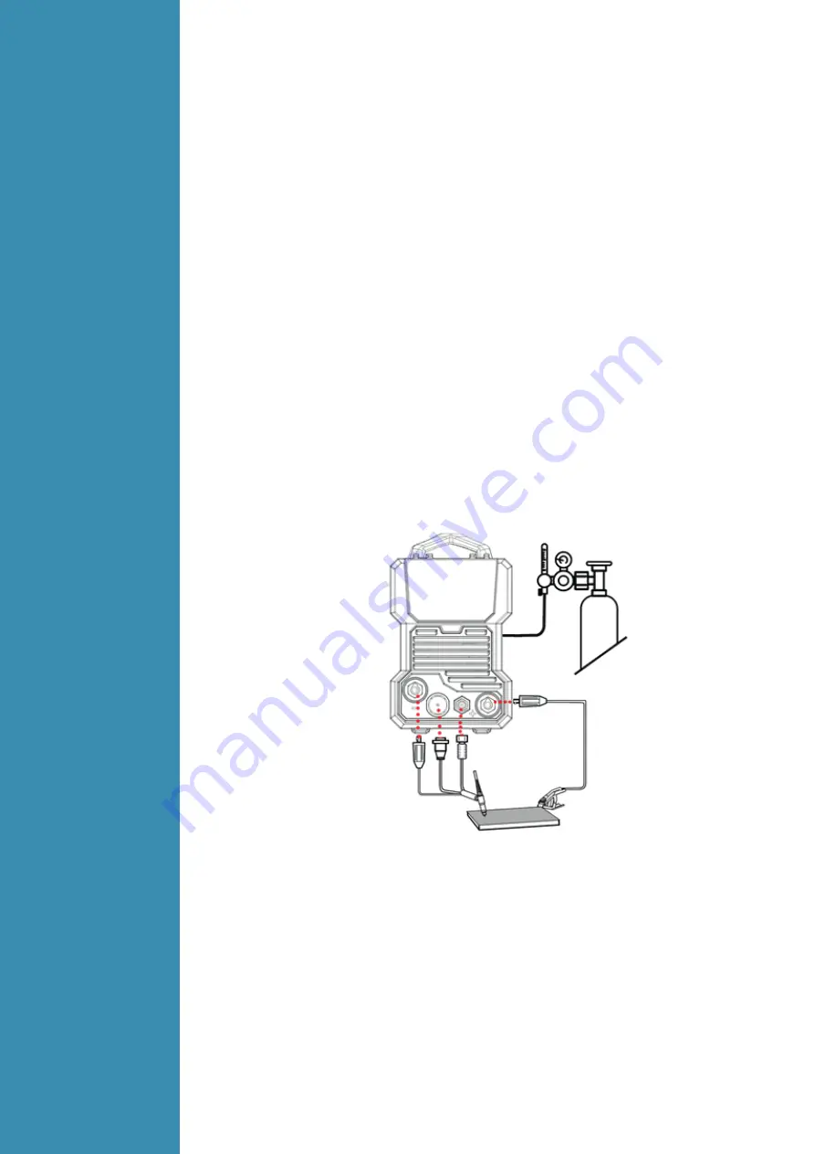
3.4.1
Set up
installation
for TIG
Welding
3.4.2
Operation
for TIG
Welding
(1)
Switch the ON/OFF Switch (located on the rear panel) to OFF.
(2)
Connect the earth lead to “+”, tighten clockwise;
(3)
Connect the earth clamp to the work piece. Contact with the work piece must be firm
contact with clean, bare metal, with no corrosion, paint or scale at the contact point.
(4)
Connect the TIG torch cable to “-”, tighten clockwise;
(5)
Connect TIG torch gas connection to the TIG gas outlet and TIG torch remote plug to remote
socket
,
ensuring all connections are tight.
(6)
Connect the gas regulator to the Gas Cylinder and connect the gas line to the Gas Regulator.
(7)
Connect the gas line to the machine inlet gas connector via the quick push lock connector
located on the rear panel. Check for Leaks!
(8)
Open gas cylinder valve and adjust regulator, flow should be between 5-10 l/min depending
on application. Re-check regulator flow pressure with torch valve open as static gas flow setting
may drop once gas is flowing.
(9)
Each machine is equipped with a power cable should be based on the input voltage welding
power cable connected to the appropriate position, not to pick the wrong voltage;
(10)
With the corresponding input power supply terminal or socket good contact and prevent
oxidation;
NOTE:
-
Secure the gas cylinder in an upright position by chaining them to a stationary support to
prevent falling or tipping.
(1)
According to the above method to install is correct, turn the power switch to the “ON” position,
the power L.E.D. light should illuminate, the fan comes on, the device work properly.
(2)
Select the 2T/4T function with the4T/2T/MMA selector switch.
(3)
Set the welding current (14), down slope (10) and gas post flow (8) as required.
(4)
The tungsten must be ground to a blunt point in order to achieve optimum welding results. It is
critical to grind the tungsten electrode in the direction the grinding wheel is turning.
(5)
Install the tungsten with approximately 3mm to 7mm sticking out from the gas cup, ensuring
you have correct sized collet.
(6)
Tighten the back cap.
(7)
Commence welding. If necessary, readjust the Weld Current control to obtain the welding
condition re-quired.
(8)
After completion of welding the Power Source should be left turned ON for 2 to 3 minutes. This
allows the fan to run and cool the internal components.
(9)
Switch the ON/OFF Switch (located on the rear panel) to the OFF.


