


2.5
Working
Principle
2.6
Volt-Ampere
Characteristic
2.4
Duty cycle
and
Over-heat
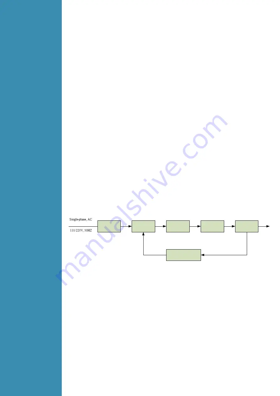
The working principle of GRAND TIG 200 DC PFC MV of welding machines is shown in the following
figure. Single-phase 110V/220V line frequency AC is rectified into DC, then is converted to medium
frequency AC by inverter device (IGBT), after reducing voltage by medium transformer
(the main transformer) and rectified by medium frequency rectifier (fast recovery diode), and is
outputted by inductance filtering. The circuit adopts current feedback control technology to insure
current output stability. Meanwhile, the welding current parameters can be adjusted continuously and
steplessly to meet with the requirements of welding craft.
GRAND TIG 200 DC PFC MV has excellent volt-ampere characteristic. Referring to the following
graph. In TIG welding, the relation between the rated loading voltage U2 and welding current I2
is as follows:
When I2≤600A
,
U2
=
10
+
0.04 I2
(
V
)
;
When I2
>
600A
,
U2
=
34
(
V
)
.
Rectify
Inverter
Medium
frequency
transformer
Medium
frequency
rectify
Hall device
Current positive-
feedback control
Three-phase, AC
DC
AC
DC
380V
,
50Hz
AC
DC
The letter “X” stands for Duty Cycle, which is defined as the portion of the time a welding machine can
weld continuously with it’s rated output current within a certain time cycle (10 minutes).
The relation between the duty cycle “X” and the output welding current “I” is shown as the right figure.
If the welding machine is overheating, the IGBT over-heat protection sensing will send a signal to the
welding machine control unit to cut the output welding current OFF and light the over-heat pilot lamp
on the front panel. In that case, the machine should not be welding for 10-15 minutes to cool down
with the fanrunning. When operating the machine again, the welding output current or the duty cycle
should be reduced.


