


GRAND
TIG 200
D C P F C M V
3
Installation
&
Operation
3.1
Layout for
the front
and rear
panel
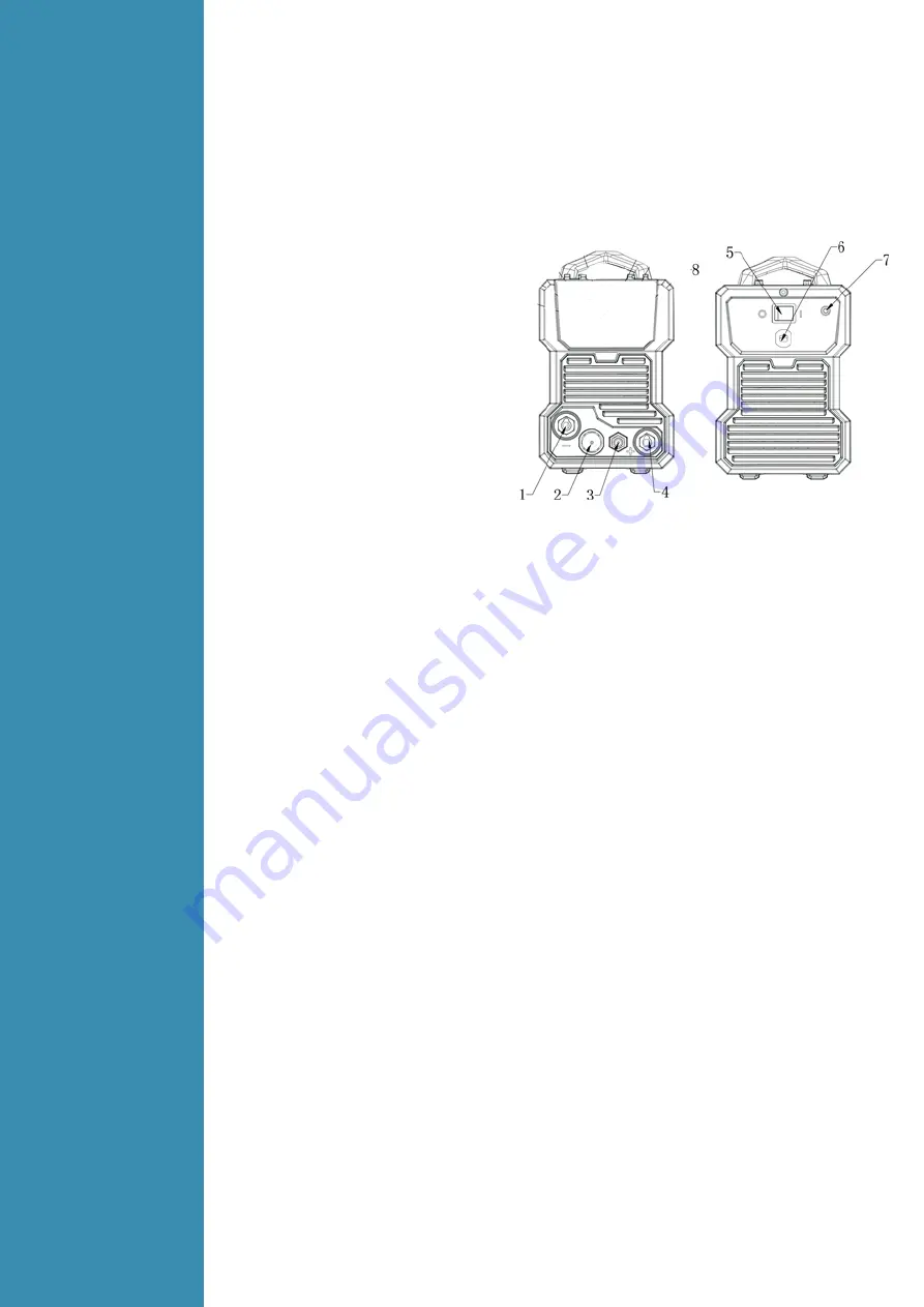
(
1
)
“-” Output terminal.
(
2
)
TIG torch remote connection socket.
(
3
)
TIG torch gas connector.
(
4
)
“+” Output terminal.
(
5
)
Power switch: control the power
Supply on and off.
(
6
)
Input power cable.
(
7
)
Inlet gas connector.
(
8
)
Parameter select/adjust Knob. *
(
9
)
Post gas flow setting indicator.. *
(
10
)
End current setting indicator.*
(
11
)
Down slope setting indicator. *
(
12
)
Pulse width setting indicator.*
(
13
)
Pulse frequency setting indicator.*.
(
14
)
Base current setting indicator.*
(
15
)
Tig Pulse Mode “ON” indicator.*
(
16
)
Tig Pulse Mode”OFF” indicator.*
(
17
)
I2: Tig Welding Current setting indicator.*
(
18
)
Pre gas flow setting indicator.*.
(
19
)
I STA: start current setting indicator.*
(
20
)
Up Slope parameter.
(
21
)
MMA Arc Force setting indicator.*
(
22
)
MMA Welding Current setting indicator.*
(
23
)
MMA Hot Start setting indicator.*
(
24
)
Welding Mode Selector ( change to MMA, Tig lift, Tig HF)
(
25
)
MMA mode indicator
(
26
)
Tig Lift mode indicator.*
(
27
)
Tig HF mode indicator.*
(
28
)
Trigger control mode selector.*
(
29
)
2T trigger mode indicator.
(
30
)
4T trigger mode indicator.
(
31
)
Alarm indicator.*
(
32
)
Voltage indicator.
(
33
)
Amper indicator.
(
34
)
Multi meter display
(
35
)
Second (time) indicator
(
36
)
Percentual indicator
(
37
)
Hertz (frequency) indicator.*
*Denotes more detailed explanation of function to follow.
Further Controls Explained
Multi Meter display (34)
Before welding this displays the setting selected or being adjusted using the control knob (8). During
welding it displays welding current. The parameter setting displayed is indicated by the LEDs beside
the display; Current (A), Time (S), Percentage (%), Voltage (V) and Frequency (Hz). If left inactive for
several seconds, display will revert back to main welding current setting.
TIG HF/ Lift Ignition Modes (26,27)
For TIG welding process, contact of the torch tungsten to the workpiece will cause contamination of
the tungsten and the workpiece that will adversely affect the weld quality, especially when the
tungsten is electrically energised.
HF Ignition
(High Frequency) sends a pulse of high energy electricity through the torch system that is
capable of ‘jumping’ between the tungsten and the workpiece, ensuring arc starting without any
contact between the tungsten and workpiece. The disadvantage of HF ignition is that the high ener-
gy electrical pulse creates significant electrical and radio signal interference, which limits its use
around sensitive electronic equipment such as computers.


